Christmas is coming up, so why not set aside an hour or two to build this blinking Christmas lights circuit?
This circuit is easy to build and it’s something you can put to use right away. I built this and hung it in the window, something my girlfriend loved!
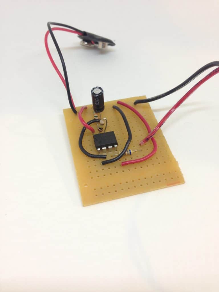
The blinking part of the circuit is made up of only 4 components. Then you’ll add as many lights as you want.
How To Blink Lights
There are several ways to blink lights. I’ve previously written about how to blink a light using transistors or a relay. Another method is to use a microcontroller.
But, I think one of the easiest ways, at least in terms of the “easiness” of building the circuit, is using a 555 timer.
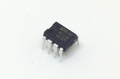
The 555 timer is a chip that you can use for creating a signal that turns on and off repeatedly. That’s exactly what you need for blinking Christmas lights!
Just connect this signal to some LEDs and a resistor to control the LED currents.
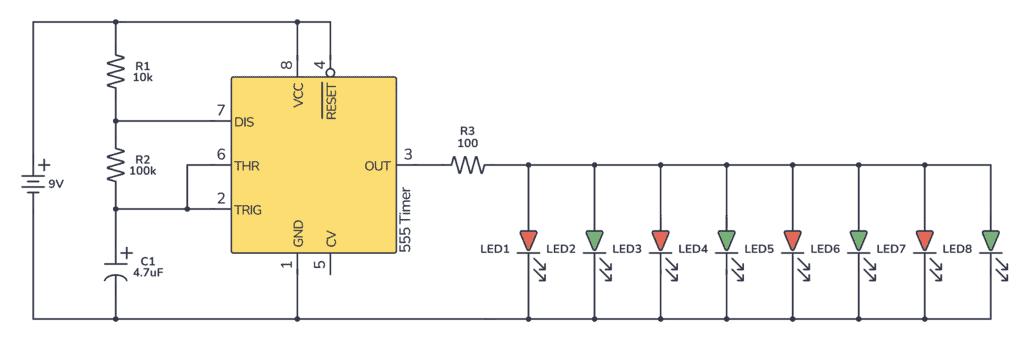
Blinking Christmas Light Circuit Diagram
In this circuit, you’ll only need 4 components + the LEDs and the resistor.

Build Something Useful This Evening
This gadget lets you use any IR remote-control to control your lamp, garden lights, heater oven, garage door, or anything else.
To get the blinking effect, you need to set the 555 Timer in astable mode. Then its output will change between 9V and 0V repeatedly.
Here’s the full circuit (see further down for the parts list and explanation):
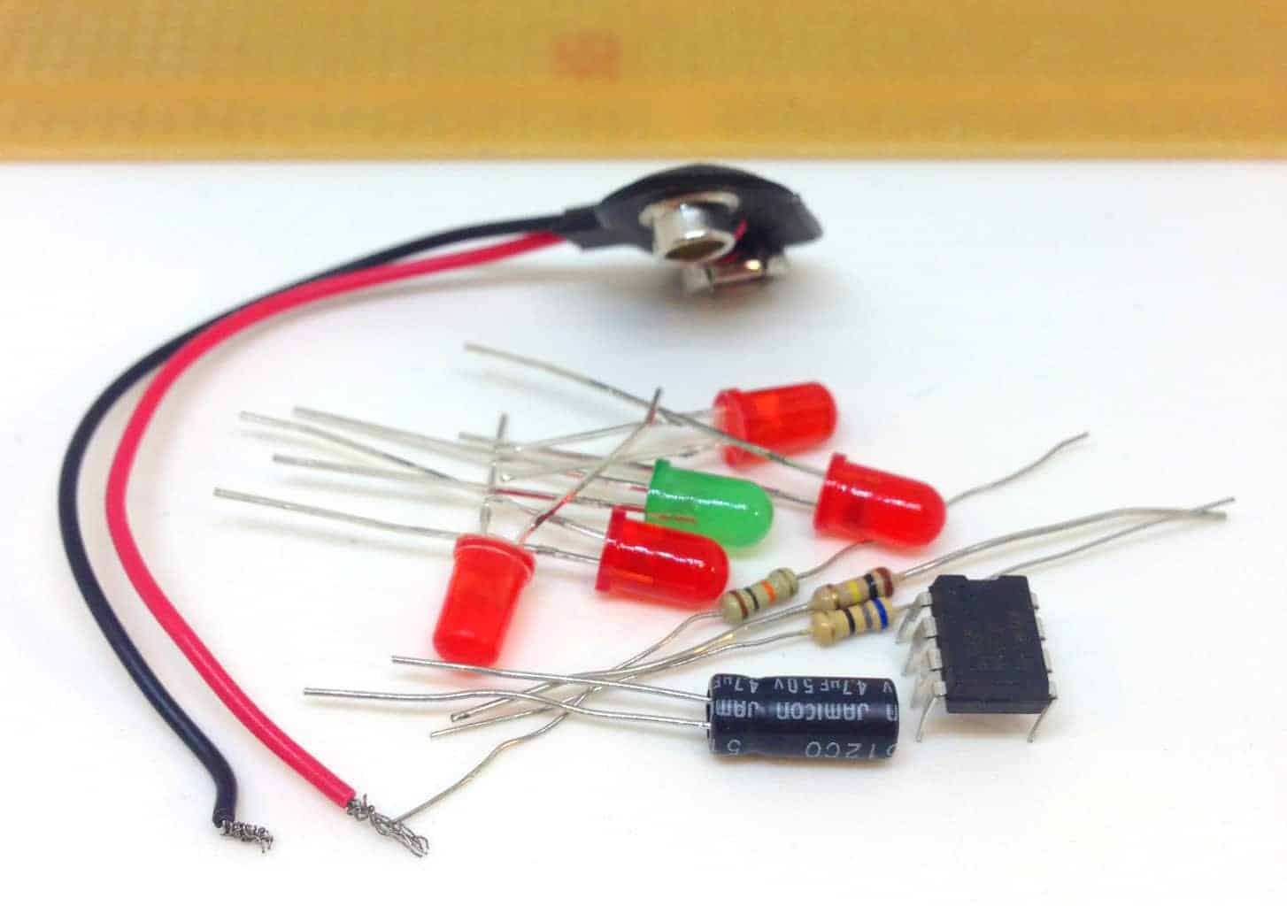
Parts List
| Part | Value | Description |
|---|---|---|
| U1 | LM555 | 555 timer |
| C1 | 4.7 µF (10V and upwards) | Capacitor |
| R1 | 10k Ohm | Resistor |
| R2 | 100k Ohm | Resistor |
| R3 | 100 Ohm | Resistor |
| L1 – L8 | Standard Output LED | Light-Emitting Diode |
Setting The Blinking Speed
Two resistors and a capacitor is all you need to set the blinking speed. You can calculate the number of “blinks” per second with this formula:

But, an even easier way is to use this calculator. Then you can try with whatever values you have at home and see what result you can expect.
With the values I’ve chosen, you should get about 1.5 blinks per second. And the time the LEDs are on should be about the same as the time they are off.
Setting The LED Brightness
When you light up an LED you should always use a resistor, so that you can control how much current that goes through it.
10-15 mA is usually a good current amount for standard output LEDs. In this circuit, you have eight of these in parallel. That means you need 80-120 mA in total for the eight LEDs. This also means you want this much current to flow through the resistor. The current going through the resistor will be the amount of current that will be shared among the LEDs.
If this reasoning does not make sense to you, I recommend you read my article What You Need to Know About Current, Voltage and Resistance.
The LEDs I used had a forward voltage of about 2V. So, a 100 Ohm resistor is a good match. You can learn how to calculate the correct resistor value for any LED in my article about current limiting resistors.
If you’re thinking about adding more LEDs, keep in mind that the 555 timer only supports around 200 mA of current. For example 20 LEDs with 10 mA.
Soldering the LEDs
I used a cable from some old headphones to connect the LEDs. Then I used heat shrink tube to cover up the solder joints.
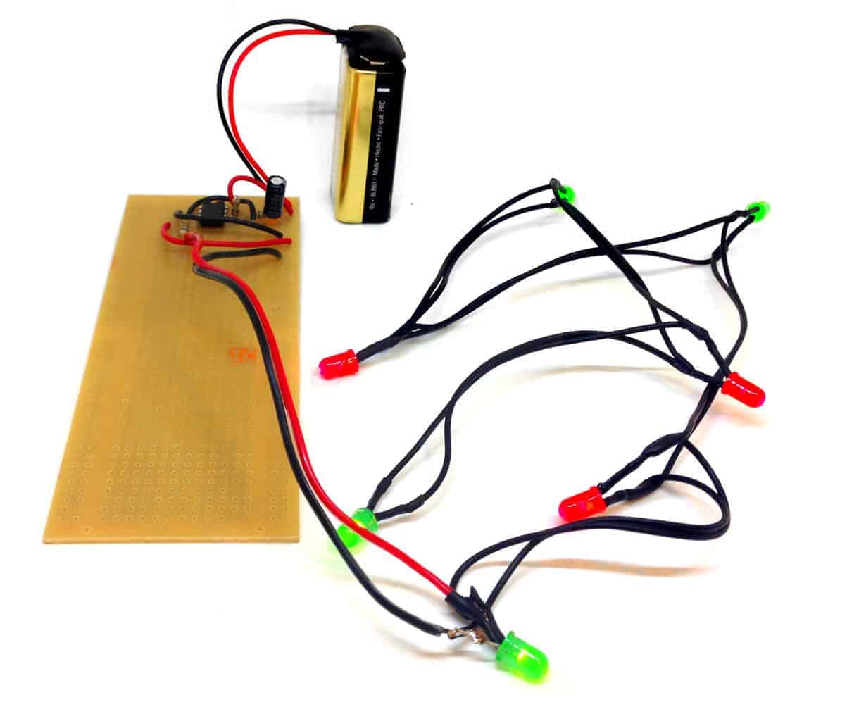
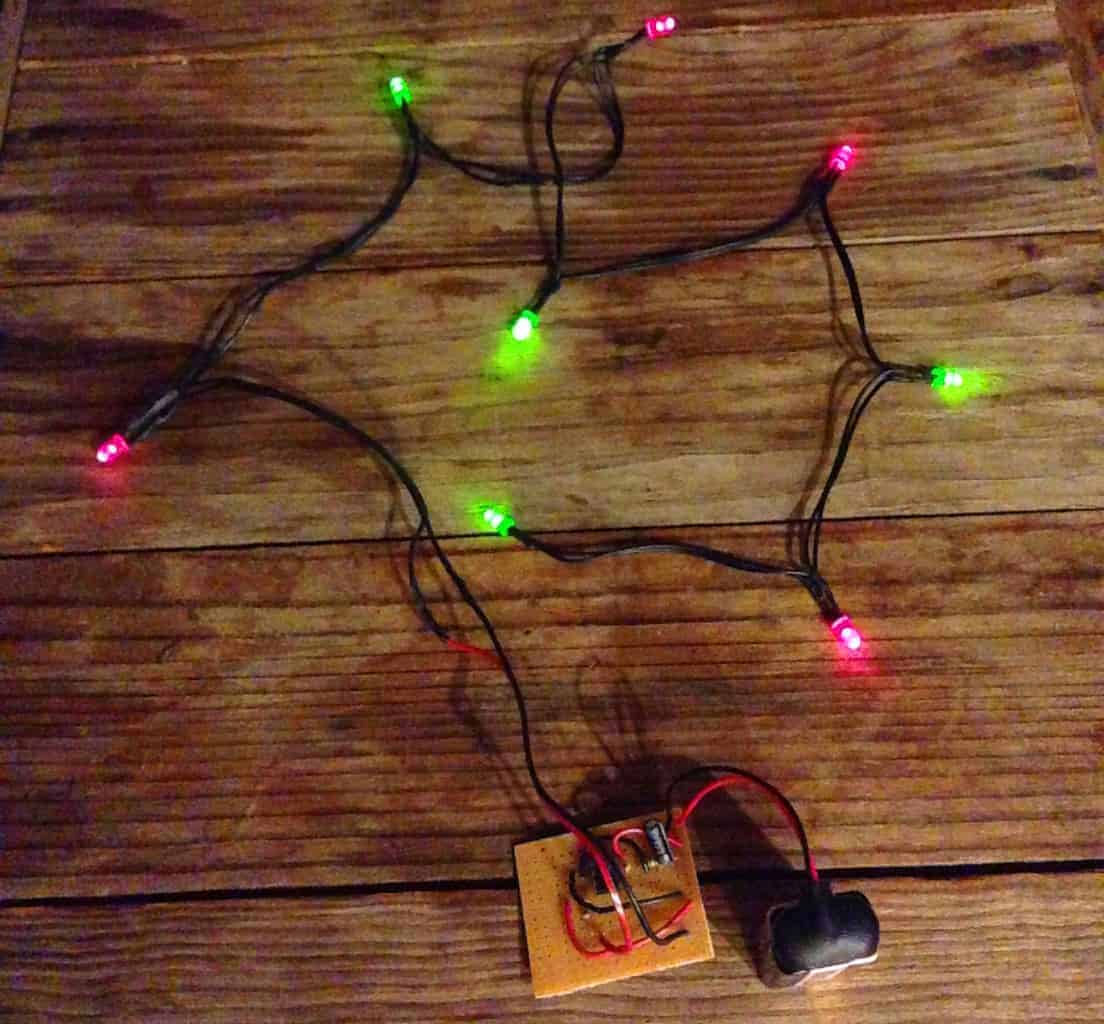
My Blinking Christmas Lights
If you built this circuit, let me know in the comment field below. Also, for any questions about modifications or anything, use the comment field below.
More Circuits & Projects Tutorials
Build Something Useful This Evening
This gadget lets you use any IR remote-control to control your lamp, garden lights, heater oven, garage door, or anything else.