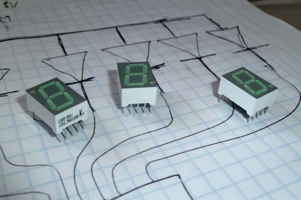
This digital stopwatch circuit is a circuit I built for testing some 7-segment displays. It consists of four displays that I control using a microcontroller. The microcontroller counts and makes sure the correct LED segments on each display is lit up.
Check out the video below to see how I built it.
Components Used For The Digital Stopwatch Circuit
- LSHD-5601 7-segment display x 4
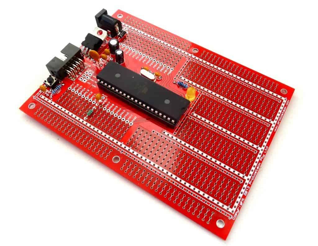
- Protostack development board (with an ATMega32 microcontroller)
I didn’t use many components to build the digital stopwatch circuit. Only some 7-segment displays and a microcontroller development board. The microcontroller board is a development board from Protostack that I have evaluated earlier.
In addition to this, I used a lot of wire to connect all the pins from the display to the microcontroller.
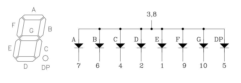
7-segment Displays
The 7-segment displays are simple components. Inside they have 7 Light Emitting Diodes (LEDs) that may be combined to display any number from 0 to 9. (Actually, the displays I used also has an LED for a dot, but I didn’t use it in this project.)
To light an LED you should always use a current limiting resistor. This controls the amount of current going through the diode.
Each LED-segment will draw about 15 mA of current. If all LEDs were ON at the same time, the digital stopwatch circuit would draw 7 x 4 x 15 mA = 420 mA. And I would need one resistor for each LED. That means 28 resistors. But that would be a waste of power and resistors.

Build Something Useful This Evening
This gadget lets you use any IR remote-control to control your lamp, garden lights, heater oven, garage door, or anything else.
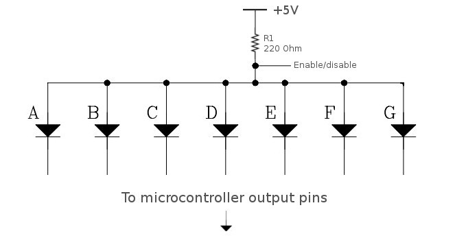
Instead I chose to only have one LED ON at any given time. And then switch among each LED really fast so that it seems like they are all ON at the same time. This way, I only needed one resistor for the display. And the display would draw only 15 mA of current.
I chose to use a 5 volt power supply. And I wanted 15 mA through the LEDs. The LED’s have a voltage drop of 2.1 volts. By using Ohm’s law I got:


I had some 220 Ohms resistor, so I chose them.
Connecting A Display To The Microcontroller
To control the 7-segment display, I connected the cathode of each LED to an output pin of the microcontroller.
When I set an output pin LOW, current flows through the LED and turns it ON. When I set an output pin HIGH, no current flows and the LED will be OFF. This is because there is no voltage potential between the anode and cathode of the LED.
Connecting Displays In Parallel
I wanted to reduce the amount of output pins I needed for the displays. So I decided to connect two and two displays in parallell. I would use the same 7 output pins to control two displays.
I used the same principle as with each segment in a display – only use one display at any given time. And switch between them really fast so that is looks like they are both on at the same time.
To enable and disable a display, I connected an IO pin to the common anode of the display.
To enable a display, I would configure the pin to be an input pin (and thereby not affect the circuit). To disable a display I would configure the pin as output and set it low (thereby making all the current flow through the resistor to ground instead of through the LED).
Programming The Microcontroller
The program I made for the digital stopwatch circuit consists of two parts. A timer part that updates 4 variables to contain the correct numbers for each of the four displays. And a part for turning ON and OFF the correct output pins to display the numbers from each of the variables in each of the displays.
Download the code and Makefile here. (Made for avr-gcc)
I programmed the microcontroller and here is the finished digital stopwatch circuit: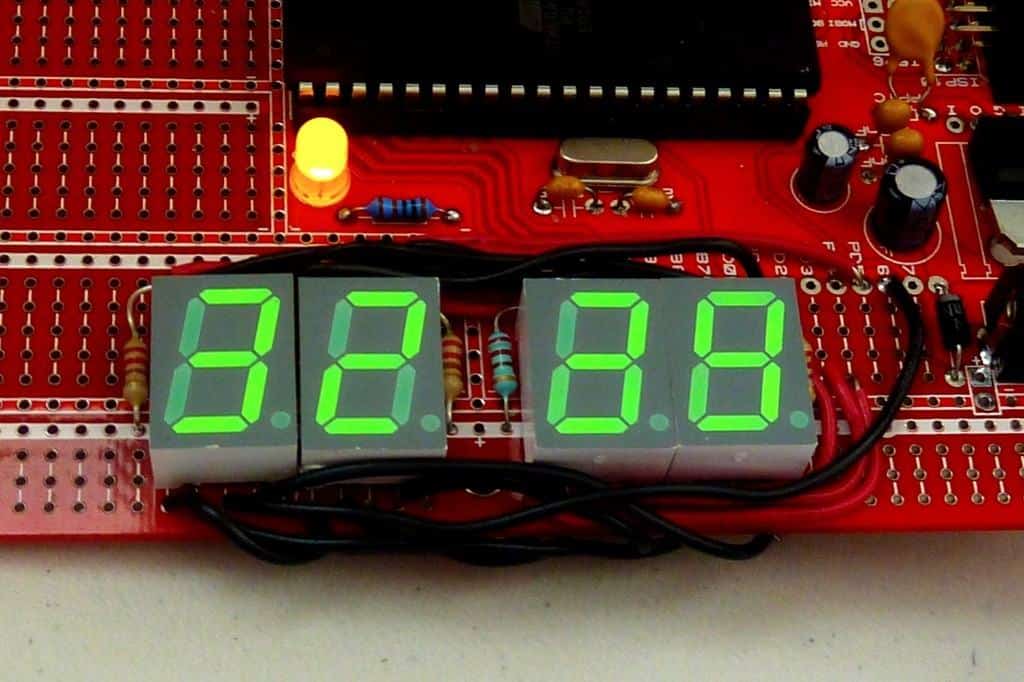
More Circuits & Projects Tutorials

10 Simple Steps to Learn Electronics
Electronics is easy when you know what to focus on and what to ignore. Learn what "the basics" really is and how to learn it fast.