A capacitor is a basic electronic component that works like a tiny rechargeable battery with very low capacity. Capacitors are used to create oscillators, time delays, add a power boost, and much more.
Like most components, the easiest way to understand how a capacitor works is to see with your own eyes what it does in a circuit.
When I started learning electronics as a teenager, this was the first component I learned about. The way my father explained it to me made it easy to understand even though I had no understanding of the basics of electronics.
In this guide, I’ll show you how a capacitor works so that you’ll be able to understand what it does in circuits, and how you can use it in your own projects.
Covered in this guide:
- What Is a Capacitor?
- How Capacitors Work
- Charging a Capacitor
- Types of Capacitors
- What Are Capacitors Used For?
- Typical Capacitor Values
What Is a Capacitor?
A capacitor is made up of two metallic plates with a dielectric material (a material that does not conduct electricity) in between the plates. And there’s actually no more magic to it. It’s that simple and you can even make your own capacitor by using two sheets of aluminum foil with a piece of paper in between.
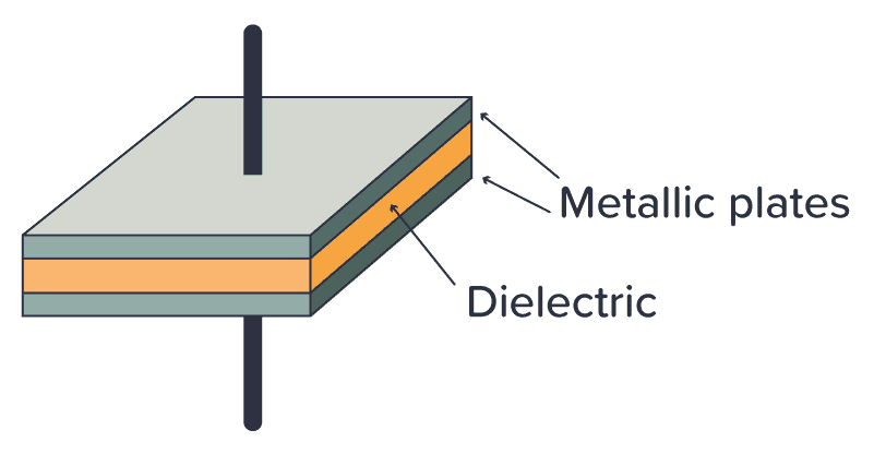
When you apply a voltage across the two plates, a current flows as the voltage tries to push electrons through the capacitor. But electrons can’t flow through the dielectric between the plates, so instead the electrons will build up on one plate and leave the other plate.
Eventually, the side where the electrons gather won’t have room for more electrons, so the current stops flowing. When that happens, the capacitor is fully charged. The amount of electric charge the capacitor can hold is called its capacitance.
Electrons don’t like being crowded together on one plate. They want to go over to the side with fewer electrons. So if you provide a path for the electrons to flow (for example by connecting a resistor between its legs) the electrons will flow back to the other side until there’s an equilibrium of electrons on both sides of the capacitor again.

10 Simple Steps to Learn Electronics
Electronics is easy when you know what to focus on and what to ignore. Learn what "the basics" really is and how to learn it fast.
How Capacitors Work
I like to answer the question of “How does a capacitor work?” by saying that a capacitor works like a tiny rechargeable battery with very low capacity.
But a capacitor is usually charged and discharged in a fraction of a second. So it’s not used for the same purpose as a battery. Instead, it’s used for things like adding a time delay, creating oscillators, and as tiny backup generators for microcontrollers.
Check out the video below to see how the capacitor works:
A Simple Capacitor Circuit
If you want to understand how the capacitor works without reading theory and formulas – then build this circuit:
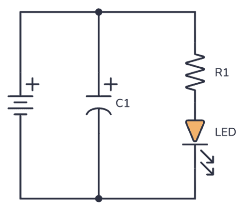
You can use a 9V battery, a standard Light-Emitting Diode (LED), and a 1000 µF capacitor. The resistor value can be around 500-1000 ohms.
Connect the battery, and you should see the LED turn on. Nothing special yet.
But when you disconnect the battery, something interesting happens… The LED stays lit for a few more seconds without being connected to the battery!
This happens because the capacitor is first charged by the battery. When you disconnect the battery, the stored charge in the capacitor flows through the resistor and LED and thereby keeping the LED on for a few more seconds, until the capacitor is discharged.
So the capacitor works similarly to a battery – it can be charged and discharged.
Charging a Capacitor
If you want to get a really good understanding of capacitors and how to use them in your circuits, there are two important things you need to know:
- What happens to the voltage across the capacitor when you charge it?
- What happens to the current through the capacitor when you charge it?
The Voltage Across a Capacitor
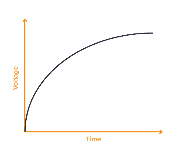
If you charge a capacitor from a 9V voltage source, the voltage across the capacitor will eventually become 9V – but not immediately. At the moment when you start charging it, the voltage will start at 0V.
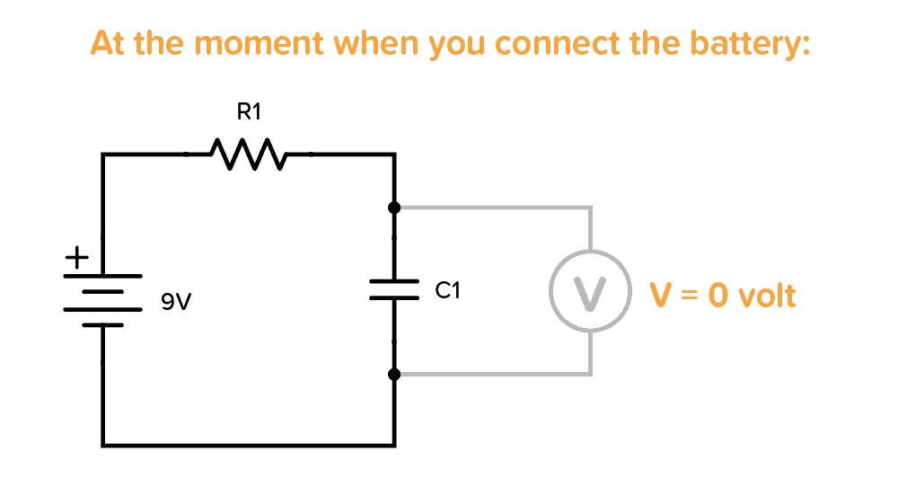
But the voltage increases quickly, so if you try to measure it with a multimeter, you won’t be able to read 0V.
After some time, when it is fully charged, the voltage across it becomes 9V (or whatever voltage you used to charge it):
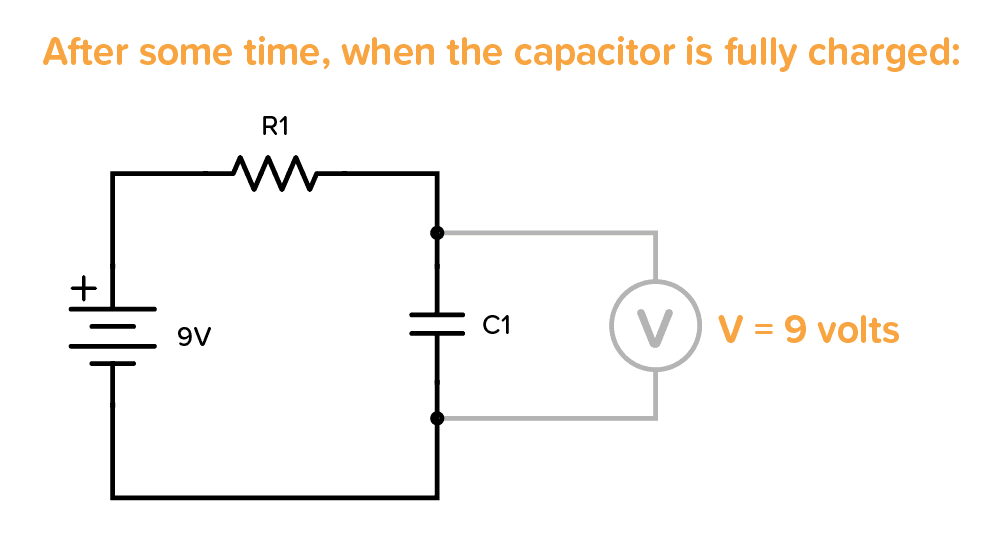
The voltage increases quickly in the beginning, then slowly at the end. The time it takes to charge the capacitor depends on how much current is flowing. In the example above, it would be determined by the resistor R1.
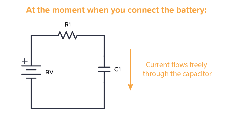
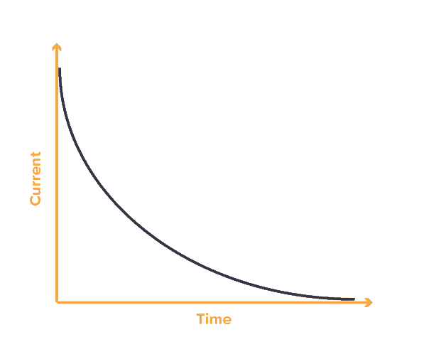
The Current Through a Capacitor
When you start charging a capacitor, the current flows freely without any resistance in the very beginning.
As the capacitor charges, the resistance increases so that less and less current can flow. When the capacitor is fully charged no more current flows through it:
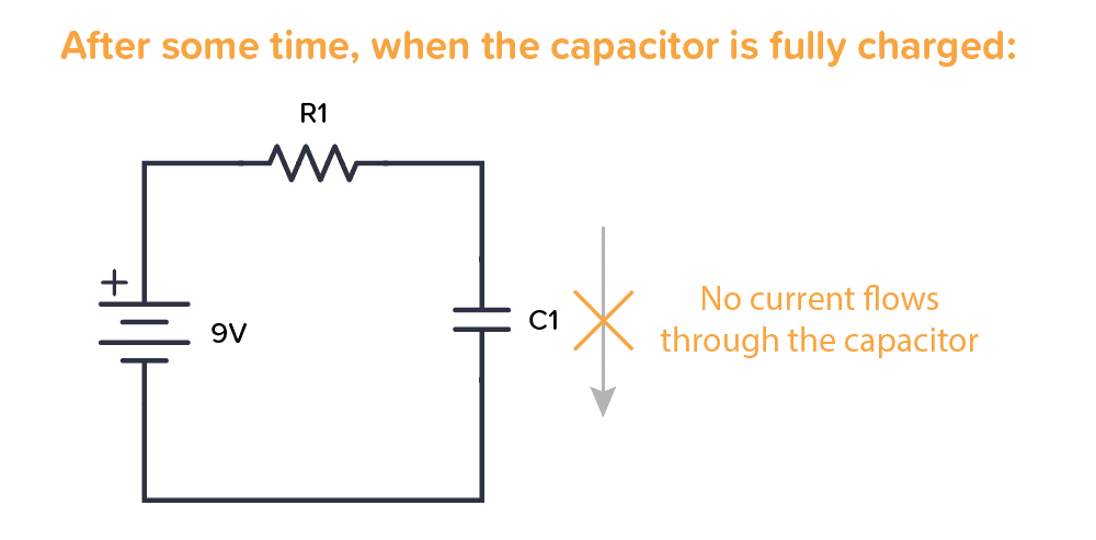
Here’s a simplified graph that shows how the current slows down with charging time:
Types of Capacitors
There are many different capacitor types. But when you start out, the main thing to remember is the difference between a polarized and a non-polarized capacitor.
A polarized capacitor needs to have its positive side connected toward plus, and the other side toward minus. Otherwise, you might destroy it. This is a side-effect of how large-value capacitors are made.
A non-polarized capacitor can be connected either way, it doesn’t matter.

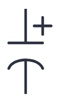
You can recognize one or the other in a schematic diagram by looking at the capacitor symbol. The polarized capacitor will have a plus marking.
Polarized vs Non-Polarized Capacitors
A non-polarized capacitor can be used, even if the schematic for the project you’re building calls for a polarized capacitor. But not necessarily the other way around.
If you need a polarized capacitor, you need something called an electrolytic capacitor. The most common types are Aluminium and Tantalum. Aluminum is the cheapest of the two. But if you need a smaller and more durable capacitor, you should choose the Tantalum type.
If you need a non-polarized capacitor, the most common types are Ceramic and Film.
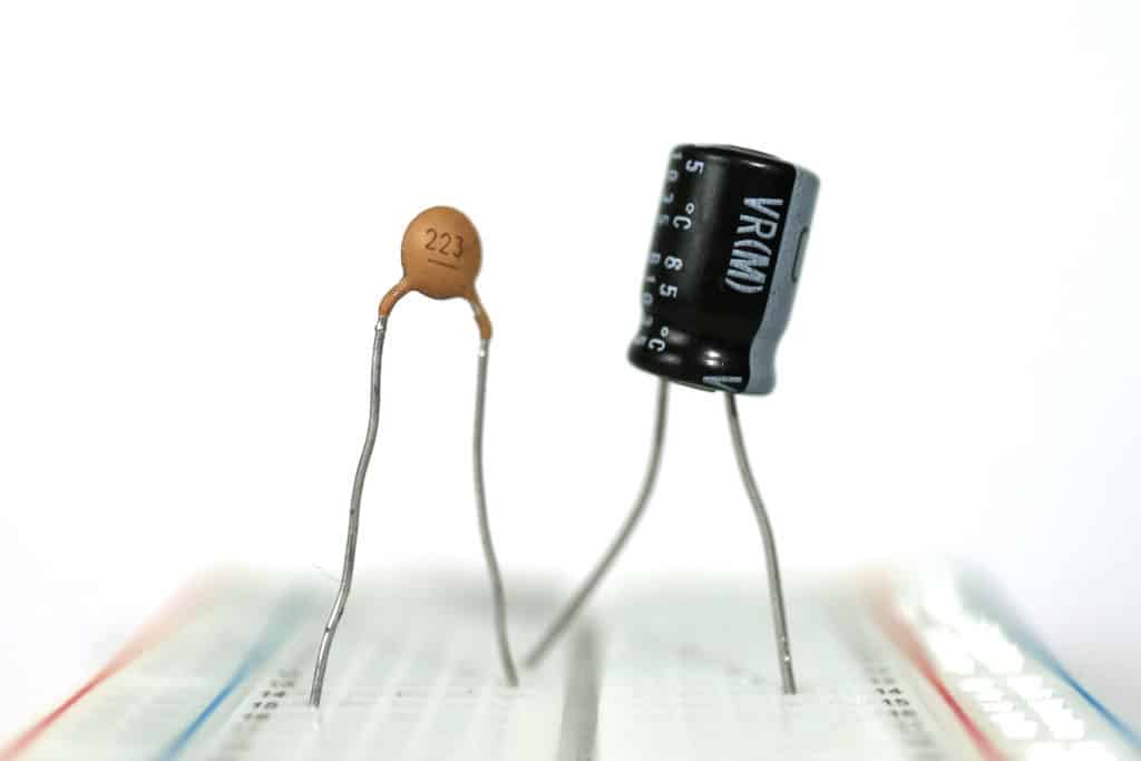
Ceramic capacitors are small and cheap. It’s the most common choice for non-polarized capacitors. But if you have any special requirements like low tolerance, high reliability, or a capacitor that is able to operate under high temperatures, then choose a Film capacitor.
In the photo below you can see a ceramic capacitor on the left and an aluminum electrolytic capacitor on the right:
What Are Capacitors Used For?
Capacitors are used for a lot of things, such as:
- Adding a time delay in a circuit
- Making oscillators (for example to make a light blink)
- Creating audio filters (such as low-pass and high-pass filters)
- Remove ripple in a power supply
- Adding short bursts of energy (for example to power the flash of a camera)
- Stabilizing the voltage supply of a microcontroller
…and much more. I’ll go through a few specific circuit examples below that you can use to improve your understanding of the capacitor.
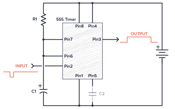
Example 1: Add a Time Delay
In this example, when the input signal goes low, the output from the 555 timer goes HIGH for a certain period of time before going back to LOW. You could for example use it to turn on the lights on your porch for 2 minutes every time an IR sensor detects that there is someone present.
In this circuit, it’s the capacitor C1 that adds the time delay. All the 555 timer does is provide the logic to check the voltage level across the capacitor against a threshold level, then turn the output on or off accordingly.
Example 2: Create an Oscillator (Blinking an LED)
In this blinking LED example circuit, the voltage across the capacitor is interpreted as either a 1 (HIGH) or a 0 (LOW) by the NOT gate.
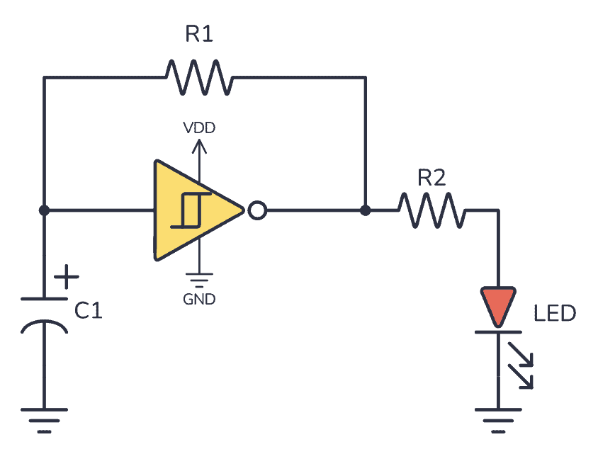
The output becomes the opposite of the input. So if the input is LOW, the output is HIGH. When the output is HIGH, the output voltage will start charging the capacitor so that it eventually also ends up HIGH. But when it does, the output will switch to being LOW. When the output is LOW, it will make the capacitor start discharging so that it eventually also ends up being LOW.
And the process repeats.
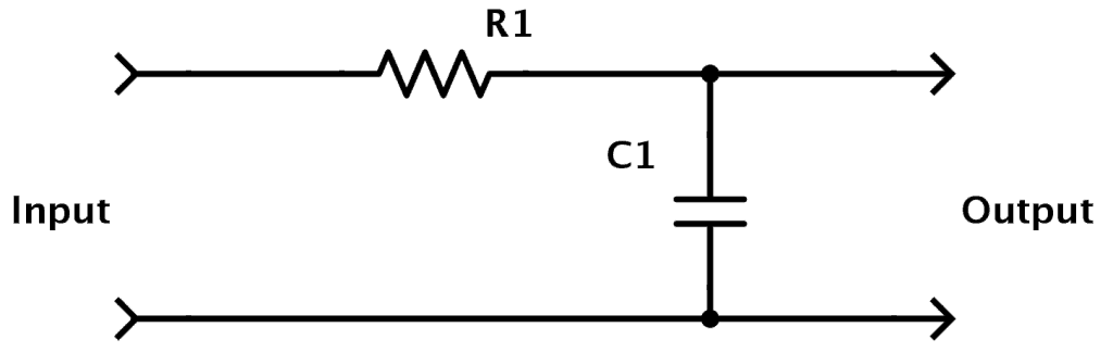
Example 3: Design Audio Filters
You can combine capacitors and resistors to form filters. A filter removes specific frequencies from an audio signal and lets others pass through. For example, if you want to remove high frequencies and let the lower frequencies pass through (e.g. in a sub-woofer), you can build a low-pass filter:
Example 4: Decoupling Capacitors for Microcontrollers
Imagine a typical alarm clock, powered by the electrical outlet on the wall in a house. If the power goes down, most alarm clocks have a backup battery that will take over and power the alarm clock until the power comes back on so that the time is not reset.
Well, in electronic circuits capacitors are used in a similar way:
If you have a circuit with a microcontroller running some code and the supply voltage to the microcontroller drops for only a split second, the microcontroller stops what it is doing and restarts. That can cause all sorts of problems, so you don’t want this.
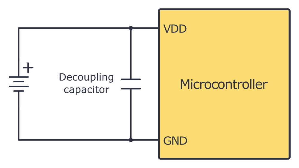
By using a capacitor, the capacitor can supply power for the microcontroller for a short period so that the microcontroller doesn’t restart. This way it will filter out noise on the power line.
A capacitor used for this purpose is called a decoupling capacitor.
Typical Capacitor Values
You have two important values for capacitors; capacitance and voltage rating.
The capacitance value of a capacitor is its “capacity” to store energy. A higher capacitance value means it can store more energy than a lower value. It is given in Farads (F).
The voltage rating is the maximum voltage a capacitor can handle. So if you have a circuit where the voltage across the capacitor can reach 12V, you need a capacitor with a voltage rating of 12V or more. It is recommended to use a capacitor rated for more than 12V so that you have some safety margin.
The capacitance value is given in Farad (F). But 1 F is a very high value. Usually, capacitor values are given as microfarad (µF), nanofarad (nF), or picofarad (pF). In the table below, you can see these values written out:
| Prefixes | Compact Value | Written-Out Value |
|---|---|---|
| 1 F | 100 F | 1 Farad |
| 1 µF | 10-6 F | 0.000001 Farad |
| 1 nF | 10-9 F | 0.000000001 Farad |
| 1 pF | 10-12 F | 0.000000000001 Farad |
If you look closely, you’ll see that for example, 100 nF is the same as 0.1 µF. This is good to remember. Because it’s very common to use both 0.1 µF and 100 nF to describe the same value.
Identifying A Capacitor Value
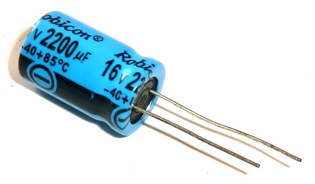
On big aluminum capacitors, the values are usually written out in cleartext. For example, if it says 2200 µF 16V, that’s the capacitance value and the voltage rating.
But often on smaller capacitors, you instead have cryptic numbers. Like 102, 223, or 474. In these cases, the first two numbers make up the base pF value, and the last is the number of zeroes you add after:
102: 10 pF with 2 zeroes after is 1000 pF. Which is the same as 1 nF.
104: 10 pF with 4 zeroes after is 100000 pF. Which is the same as 100 nF. Or 0.1 µF.
223: 22 pF with 3 zeros after is 22000 pF. Which is the same as 22 nF.
474: 47 pF with 4 zeroes after is 470000 pF. Which is the same as 470 nF. Or 0.47 µF.
Learn more about capacitor values, prefixes, standards, and calculations here.
More Capacitors Tutorials
10 Simple Steps to Learn Electronics
Electronics is easy when you know what to focus on and what to ignore. Learn what "the basics" really is and how to learn it fast.

