 Because of a mistake made by yours truly, I decided to write about how to repair electronics.
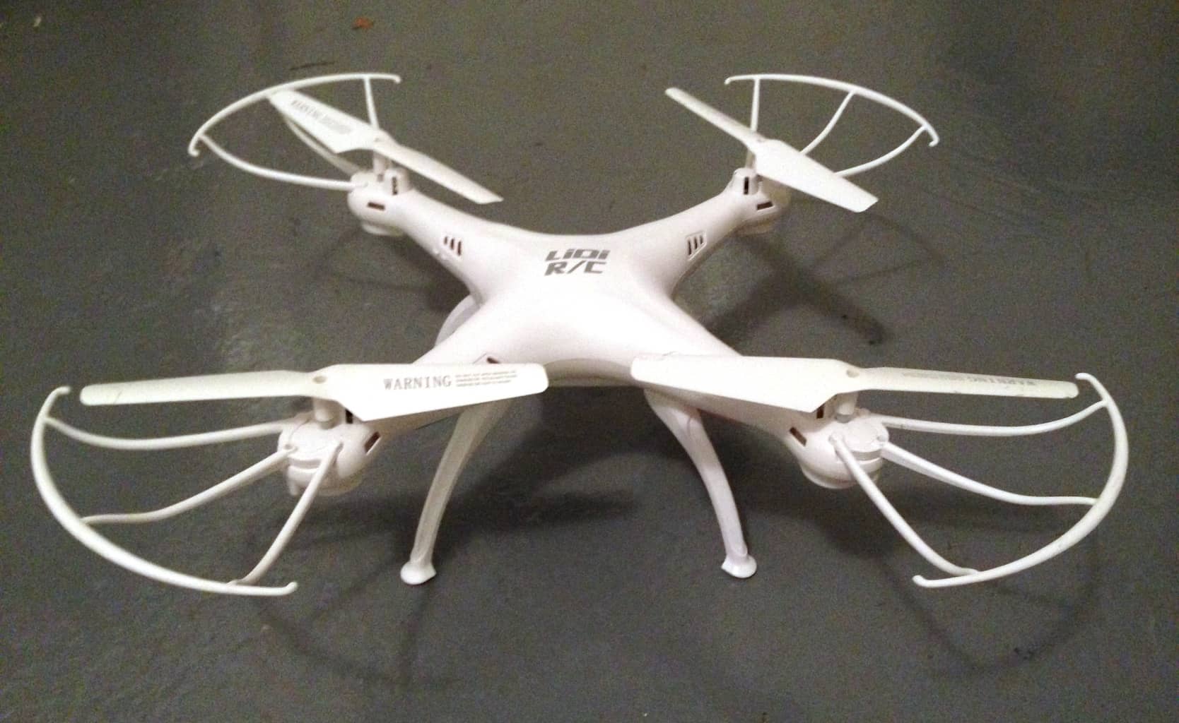
You see, I got a drone for Christmas this year.
It was really windy outside that day. However, I was so excited to take it for a spin!
I found a big open space, put my drone down on the ground, and started the take-off.
I only got the drone a couple of meters up into the air before the wind took charge. It blew it further and further away from me until it crashed into a tree and fell to the ground.

This didn’t stop me though. I started over again.
But the same thing happened. It was impossible to control the drone in the strong wind!

Get Our Basic Electronic Components Guide
Learn how the basic electronic components work so that circuit diagrams will start making sense to you.
After maybe ten crashes, one of the rotors stopped working!
Noooo!
I hoped it was just a flat battery, but it was not.
Many people ask me for tips on how to repair electronics, so I decided to write about how I fixed my drone.
What Is The Problem?
Before I could fix my drone, I had to find the root of the problem. One motor was not running, why?
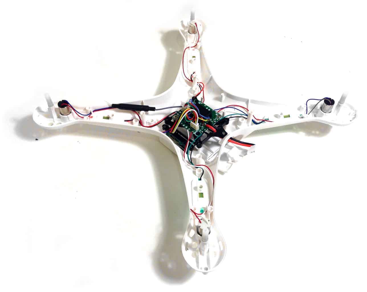
I started by carefully unscrewing all the screws to open the chassis.
When I opened the chassis I got an immediate positive surprise. Do you see it?
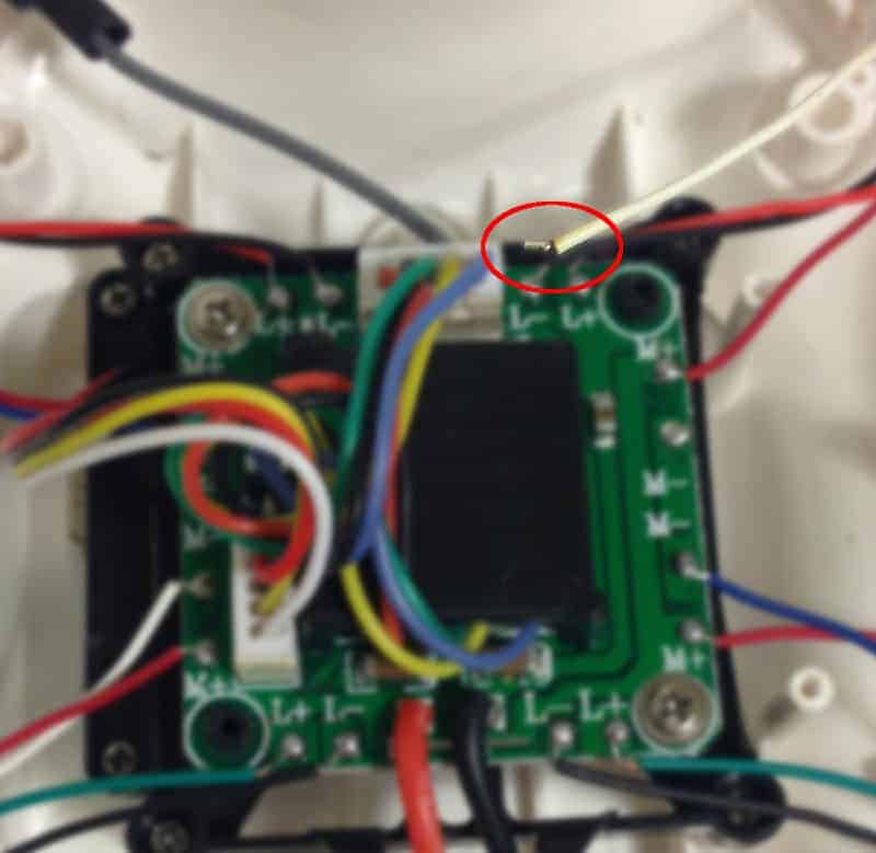
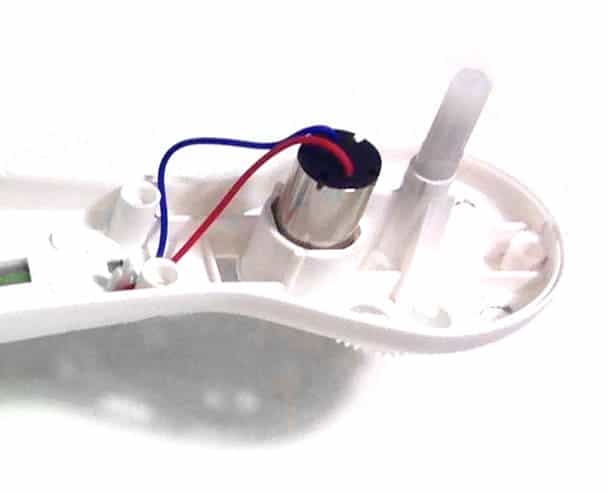
One of the wires of the motor that was not working was loose!
Wow, I couldn’t believe it would be so easy.
“Now I can just quickly solder the wire back on and everything will be fine”, I thought.
Unfortunately, it turned out to be more complicated…
I resoldered the loose wire and connected the battery. Without even turning on the power button, the motor I had “fixed” started spinning like crazy.
Strategies On How To Repair Electronics
It turned out the loose wire was not the problem. It definitely was a problem, but resoldering it did not repair my drone.
What to do?
My experience in building electronics was about to become very useful…
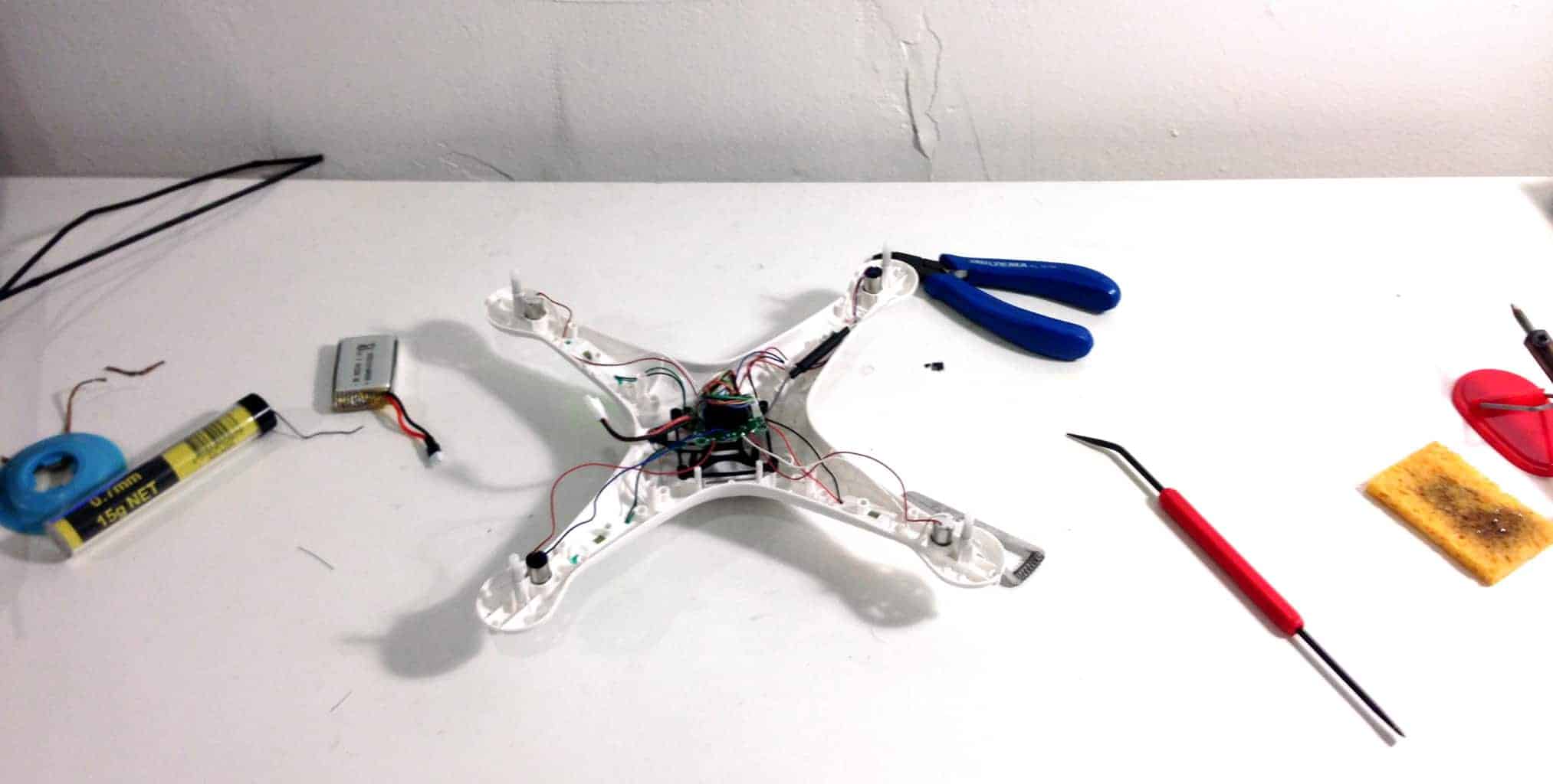
When I build a new thing, 4 out of 5 times it does not work on the first try. One of my strategies for finding faults is to measure voltages around the board.
From my circuit diagram I can select important points in the circuit that I need to check. Two obvious points to check are Vcc (or the plus connection) and ground (the minus connection in most cases).
Other important points depend on the circuit but could be the control signal to a transistor, the state of an output pin from an integrated circuit, and more.
Unfortunately, it’s not common that manufacturers of electronics give the circuit diagram for their products to the end-user. So I did not have a circuit diagram for the drone.
One thing I did have though was three working motors. By measuring the voltage on the wires of the other motors, I would know what to expect from the non-working motor. I also had plus and minus connections that I could measure to see if they had the correct voltages.
Debugging The Motor
For a motor to run, it needs to have current running through it.
For a motor to have current running through it, it needs to have a voltage drop. That is, the voltage on one side must be higher than the voltage on the other side.
Since the power button was set to off, the correct behavior of the motors would be to not run. I measured the voltages and the working motors had the same voltage as the plus connection on both wires, so they were not running.
Then I measured the non-working motor (which was running at full speed), and it turned out that the one wire that had been loose now had a voltage of 0 volts. While the other wire had the same voltage as the plus connection.
It was like connecting the two motor wires directly to the power source. No wonder the motor was running at full speed!
Testing To Find Faults
I had peeled off another layer in my search for the real problem. The voltage at one of the wires of the problem-motor was at 0V, but should have been at the same voltage as the plus. Why?
Some ideas I came up with were:
- Maybe there’s a calibration problem that makes the motor spin really fast?
- Maybe there’s a problem with the electronics controlling the motor?
I quickly ruled out the calibration theory. The motor was spinning even when the power switch was off. I didn’t see any way this could have something to do with calibration.
A very common method to control brushed DC motors is to use a MOSFET transistor. So, I drew up a simple schematic diagram for this:
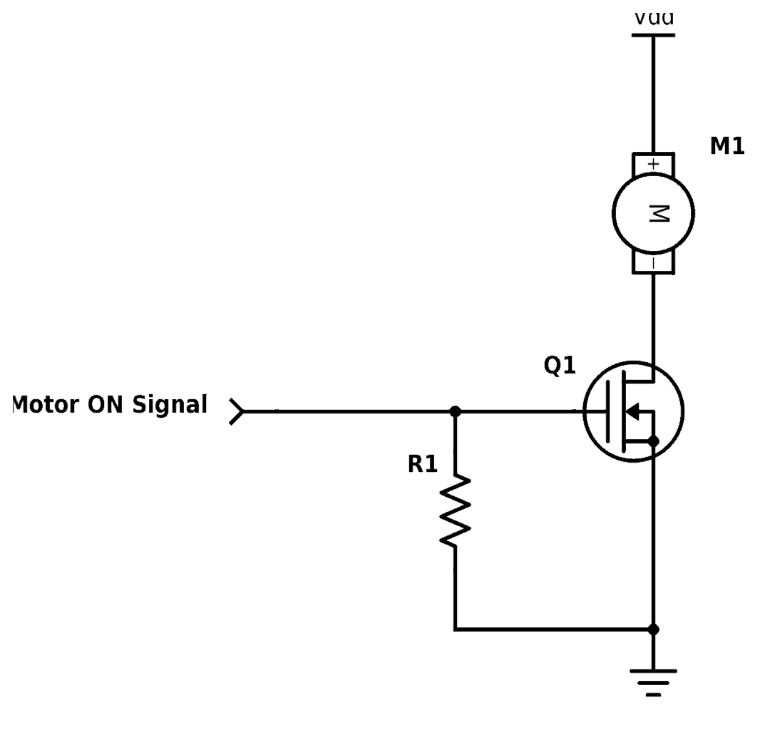
Assuming that the motor control of my drone was designed like above, I could think of two potential problems:
- The transistor was broken
- The pull-down resistor on the base/gate was shorted (*)
(*) Shorted or a short-circuit is an unintentional connection between two point.
Reverse Engineering The Circuit
Before I could investigate these theories further, I had to confirm that the circuit I drew above was correct.
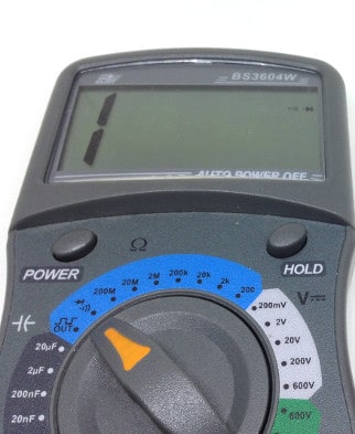
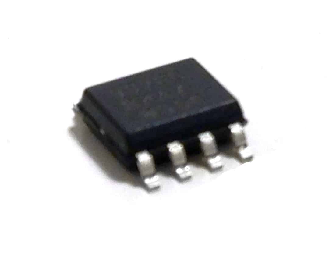
To do that, I used the continuity tester function on my multimeter to find which components were connected to the motor. I quickly found that the problem-wire of the motor was connected to an integrated circuit with the markings “9926”.
I googled around and found a datasheet. Turns out it’s a chip with MOSFET transistors. And I was able to verify that it was connected as my circuit above. Bingo!
Next, I used my continuity tester to measure between the gate and the ground. The test showed positive. That meant there was a short circuit. I checked the other motors, and none of them had this.
One of my theories was that the resistor connected between the gate and the ground was broken. Since this was the easiest theory to test out, I desoldered the resistor and measured again.
Still a short-circuit.
That could only mean that the chip was broken.
Replacing The Chip
I found a replacement chip on Element14 and ordered it. The chip cost $1. Shipping cost $30. Ah!
Anyway, the chip arrived about one week later. I desoldered the old chip and resoldered the new chip. Then I added the 10k resistor that I had removed.
Voila! The drone works again!!
How To Repair Electronics In Short
In short, here’s my recommended method on how to repair electronics:
- First, find out what is not working. In my case it was easy: One of the motors did not work.
- Next, find out why it is not working. This is the hard part. Try to find a circuit diagram for the thing you want to repair. Use a multimeter to measure voltages and look for suspicious voltages.
- From what you learn, create theories about what the cause of the problem is. Test the theories that are the easiest to test first. Continue until you find the problem.
- Then fix the problem. Sometimes you’re lucky and you only need to attach a wire that has come loose. Other times you need to replace a small and hard-to-find component.
Want to learn to repair electronics?
Check out our online course How To Repair Electronics over at Ohmify.
I’d love to hear from you: Have you ever repaired electronics? What would you like to repair? Use the comment field below and let me know your experience and questions.
More Repair Electronics Tutorials
Get Our Basic Electronic Components Guide
Learn how the basic electronic components work so that circuit diagrams will start making sense to you.

