This Arduino oscilloscope is perfect if you need an oscilloscope right now, but all you have is an Arduino.
Update: There’s an even easier way to do this now. Check out my new article on how to build an Arduino oscilloscope with 7 lines of code.
I needed an oscilloscope to debug my Radar Arduino library.
The code worked perfectly when it was not in “Arduino library”-form. But when I modified it into a library, it just didn’t work at all.
Since the radar module (from https://www.xethru.com) was using the UART, I didn’t have any way of checking what was going on.
So I needed an oscilloscope to check if there was actually any action on the UART lines.
Tools needed:
Step 1: Upload Arduino Oscilloscope Code
First of all you need some code to read the analog value from the analog input pin A0. You can do this easily by using the analogRead() function.

Free Course: Blinking a Light
Join my free email course on how to build a circuit that blinks a light. Enter your details below and you'll receive the first lesson right away:
Then you need to send this value over to your computer using the serial port. There are plenty of ways to do this. In the following code, the value is sent as two bytes with one 0xff byte in between.
This code reads an analog input and writes the value to the serial port. Upload the following code to your Arduino:
const int analogPin = A0;

void setup() {
  //Setup serial connection
  Serial.begin(9600);
}

void loop() {
  //Read analog pin
  int val = analogRead(analogPin);

  //Write analog value to serial port:
  Serial.write( 0xff );
  Serial.write( (val >> 8) & 0xff );
  Serial.write( val & 0xff );
}
This code is from https://gist.github.com/chrismeyersfsu/3270358#file-gistfile1-c
This is really all it takes on the Arduino side to make an Arduino oscilloscope. But to display the values, you need some code on your computer too.
Step 2: Install Processing
You need something on your computer to receive the values that are sent from the Arduino and display them nicely. Processing is a simple programming environment to do this.
Download processing for free from their website: https://processing.org/
Then install it on your computer.
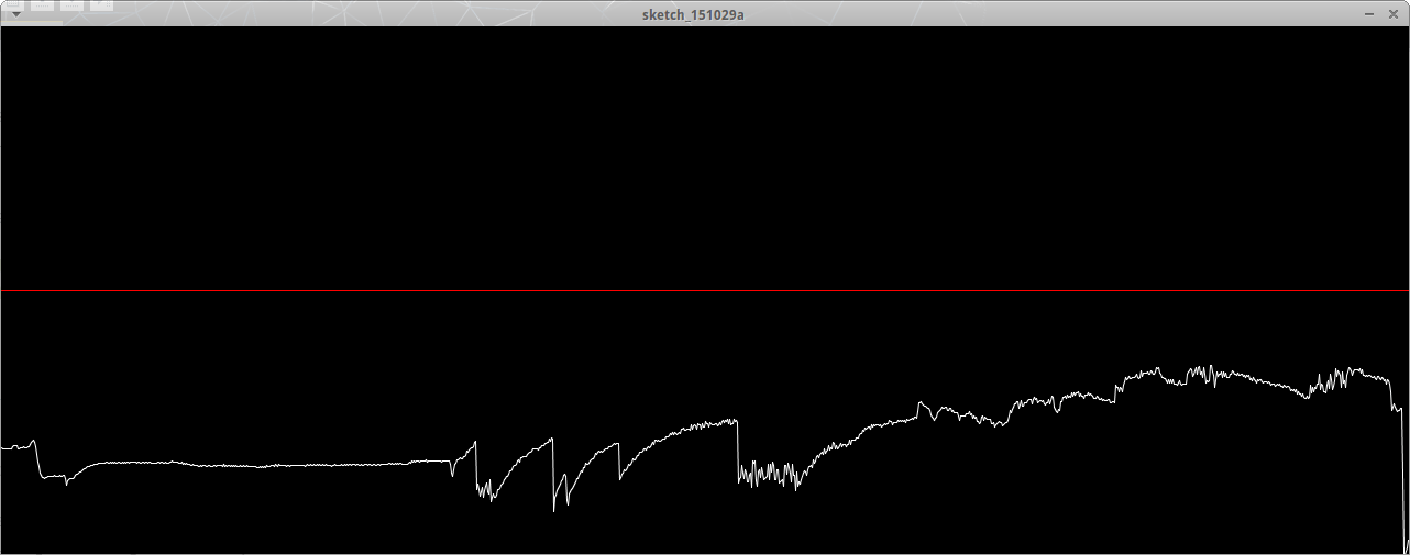
Step 3: Run Processing Code
Then, you’re ready to run the processing code. Copy and run the following code in processing to get a nice oscilloscope interface on your computer:
https://gist.github.com/chrismeyersfsu/3270419
Step 4: Test Your Arduino Oscilloscope
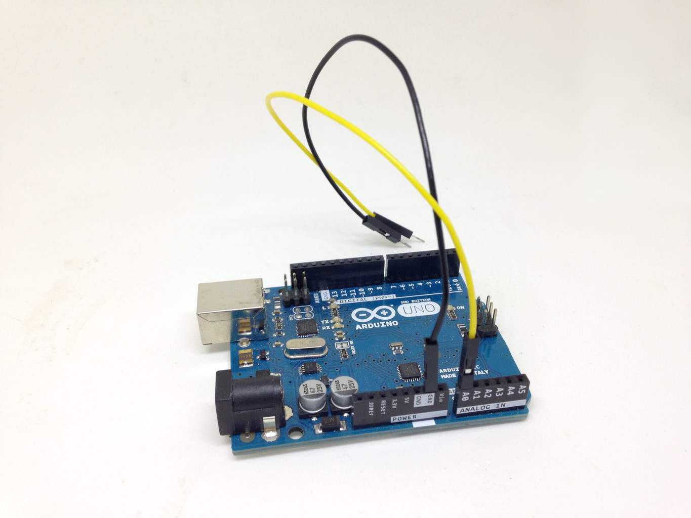
Connect two jumper wires to your Arduino. One from the ground and one from the A0 analog input.
You should now be able to use these wires to measure things and see the measurement on your computer.
Viola! You’ve just created a super simple Arduino oscilloscope.
Oscilloscopes are actually very easy to use, once you learn a few basic things: Learn how to use an oscilloscope.
More Arduino Tutorials

10 Simple Steps to Learn Electronics
Electronics is easy when you know what to focus on and what to ignore. Learn what "the basics" really is and how to learn it fast.
Hey Oyvind,
This is really a very cool way of getting around an oscilloscope, but I was wondering how accurate it is.
Hey Shamonto,
It’s not very accurate. So if you need precise measurements, this is not the way to go.
Oyvind
Cool little project, thanks Oyvind! A few thoughts…
One can get good accuracy if rather than sampling from within an indeterminately-sized loop, one instead bases the sample timing on some kind of reliably consistent clock. While you may succeed using one of the PWM outputs to trigger an external interrupt as your timer, I would say the “right way” to do this is to use the Arduino’s Timer Interrupts. Or, for those who really want serious high accuracy, a dedicated real-time clock (RTC), should be used. The DS3231 chip, can send clock ticks as fast as 400kHz over its serial I2C interface, thus your oscilloscope could sample frequencies as high as 200kHz. Not bad.
As long as sample timing is *consistent*, it’ll be accurate enough to do some fun things with, for example, an audio signal as input. Well, at least in the time domain…
Has anyone tried running an FFT on the Arduino??! :-)
Cheers.
FFT on the Arduino… what was I thinking? Of course someone has done it! :-) Very cool:
http://wiki.openmusiclabs.com/wiki/ArduinoFFT
Great input ColdCold!
And yeah, of course someone had done FFT ;)
Cheers!
Oyvind
thank you oyvind.
it’s fantastic to make such oscilloscope.
can you tell the maximum frequency and amplitude it can measure.
Hi chetan,
Maximum amplitude for the ADC is 5V. Frequency I’m not so sure about, but probably not very high…
Cheers!
Oyvind
Thank you for the great project. I am having some difficulty since I have no idea about processing software , I have followed all the steps given above but the processing software does not show any wave instead on arduino serial monitor window there are continuous stream of various symbols.
So I will be thankful if someone could help me.
Hi,
The continouos stream of symbols on the serial monitor is a good sign. At least something is coming from the Arduino.
Could it be that no wave is showing because there are no wave to show? What are you measuring?
Cheers!
Oyvind
Is there a way that you could read 3 or 4 signals at the same time? Each one above the other and from 0 to 18 volts? This way you could check 4 signals on a car engine and see if they were firing in the correct sequence? The signals only need to relate to one another.
Thanks
Yes. You need to scale down 0-18V down to 0-5V and use 4 analog inputs. So it requires a bit of modification to the code. But it shouldn’t be too hard if you’re familiar with coding.
Best,
Oyvind
Can you explain it in detail
im getting const error
im getting const error when i run the oscilloscope code in processing
I haven’t used this in over a year, but it worked when I tried it. I suggest you contact the developer from the link in the article, and he should be able to help you out.
Best,
Oyvind
Hi nice job. how can I measure my amplitude and frequency since no scale is given?
It’s been a long time since I did this. You could check out the source of the program and figure it out this way: https://gist.github.com/chrismeyersfsu/3270419
Best,
Oyvind
I am having an error arrayindexoutsidebond ???
On the github code? Then you can make a comment on the github page and let them know about the error.
Oyvind
Hello,
I have the same problem as “arsalan”.
My Arduino is sending data, which i can see on the serial monitor.
The “oscilloscope” sadly does not show anything, not even if I test it with two wires as you suggest above.
Do you have any idea how i could solve this problem?
Best regards
Florian
Hey,
It’s been a while since I’ve tried this code, so I am not sure. In the new version of the Arduino IDE there is a data-plotter included. It’s much easier to use and doesn’t require the processing code. I’ll write an article about this soon.
Best,
Oyvind
Hi,
thank you for that response! After some time of trying to get it work, I found out about the Serial plotter, really great for fast signal checks.
Best Regards
Florian
I just got this running. Very nice!
The Processing sketch was coming up with nothing, because the following line was not picking up the serial port on Windows:
port = new Serial(this, Serial.list()[0], 9600);
Changed it to the serial port for my Arduino, and it works great.
port = new Serial(this, “COM17”, 9600);
Thanks RJ!
Another trick: change the setup loop as follows, and you can hook the wire from A0 to (one at a time) pins 9, 10 and 11 to see the PWM waveforms generated by the microcontroller for different levels.
void setup() {
//Setup serial connection
Serial.begin(9600);
// Set up PWM output on pins 9,10 and 11 for different levels.
// You do it here because once it’s set up, it keeps running.
// You don’t need it in the main loop so it doesn’t interfere
// with the measurements.
// Once it’s running, attached the wire from A0 to each pin to
// see the square waveform generated by each value – 100, 150, 200.
pinMode(10, OUTPUT);
pinMode(11, OUTPUT);
pinMode(9, OUTPUT);
analogWrite(9,100);
analogWrite(10,150);
analogWrite(11,200);
}
Thanks to all that are contributing to this.
My question is what do you have running on the PC that does the display?
I have it running but the lines are all jammed together.
I am trying to get something that looks like a simple sine wave. Any frequency, any voltage.
And without digging into the code, are there any keys that will do “stuff” ?
thanks
I recommend you check out the updated article. That’s much easier and almost no code:
https://www.build-electronic-circuits.com/arduino-oscilloscope-updated/
what is the max frecuency.
Check the updated article to learn about max frequency: https://www.build-electronic-circuits.com/arduino-oscilloscope-updated/