A potentiometer is an adjustable resistor with three pins. The fact that it has three pins instead of two was confusing to me when I was starting to learn electronics. But as soon as I saw the inside of it, it all made sense.
In this guide, I’ll show you what the potentiometer looks like on the inside, the different potentiometer types, and examples of how to wire it up for different circuits.
What Is A Potentiometer?
Potentiometers are adjustable resistors used in circuits for many things, such as to control the volume of an amplifier, control the brightness of a light, and much more.
It is like the resistor. But while the resistance value of a resistor stays the same, you can adjust the resistance value of a potentiometer.
A potentiometer has three pins and the schematic symbol looks like this:

But you don’t need to use all three pins if you don’t need them. It’s totally fine to use just two pins.
Once you learn how it’s made, you’ll quickly understand how to do that. But you can also jump right to the wiring examples at the end if you just want to see some examples of how to connect a potentiometer.
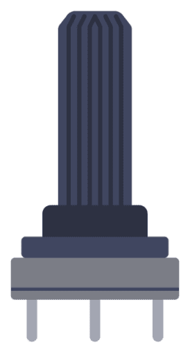
How Potentiometers Are Made
A potentiometer is made of a strip of resistive material, usually a carbon mixture. Plus a wiper that can be adjusted and placed somewhere on that strip.

10 Simple Steps to Learn Electronics
Electronics is easy when you know what to focus on and what to ignore. Learn what "the basics" really is and how to learn it fast.
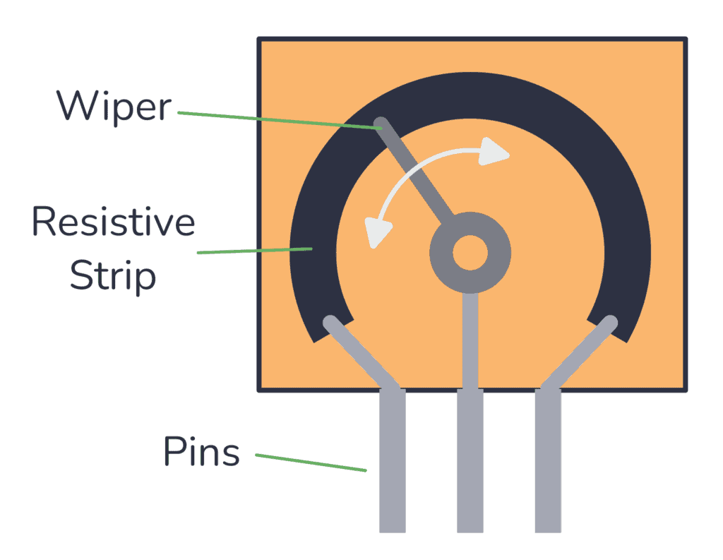
Each far side of the strip is connected to a pin. And the middle pin is connected to the wiper.
The wiper touches the strip somewhere between the two ends. The position of the wiper determines the resistance between the wiper and the side pins. You can move the point where the wiper connects to the carbon strip by turning the shaft of the potentiometer.

When you move the wiper to the left side, the resistance between the middle pin and the left pin decreases. And the resistance between the middle pin and the right pin increases.
Move the wiper to the right, and the opposite happens.
When you buy a potentiometer, you have to choose a value. For example 100k. This is the value you get if you measure the resistance between the two end pins. And it’s the largest resistance value you can get from the potentiometer.
Potentiometer Types
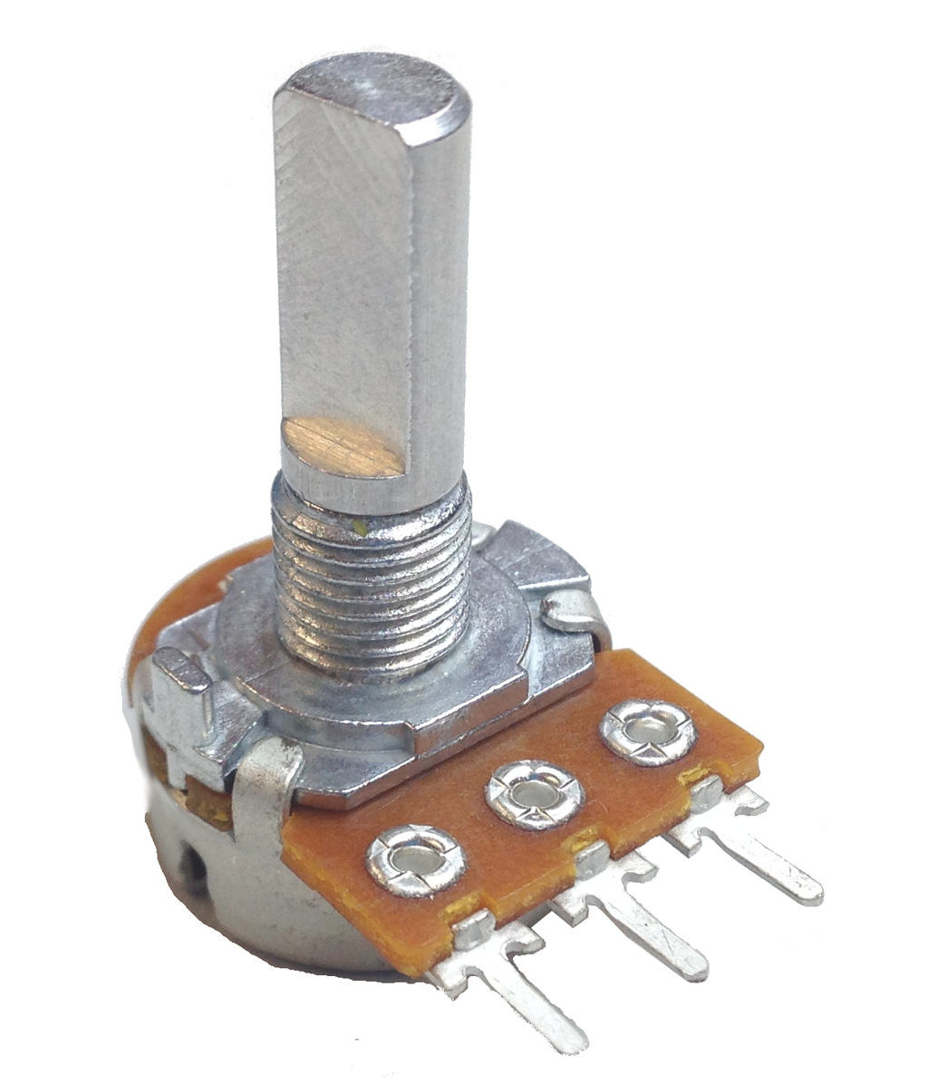
Rotary Potentiometer
This is the most common type. It has a shaft that can be turned, and the resistance changes as you turn the shaft. It’s often used for adjusting the volume on guitar pedals, audio amplifiers, and other audio equipment.
This type of potentiometer can be found with values that change linearly or exponentially. The exponential version of the pot is usually used for adjusting audio volume.
Dual or Stereo Potentiometer
This is the same as the rotary potentiometer, just that it contains two potentiometers operated by a single shaft. This makes it possible to control two channels at the same time, such as the left and right channels of a stereo system.
Linear or Slide Potentiometer
A slide (or linear) potentiometer looks like a slider and you change the resistance as you move a slider or wiper in a straight line.
This type of potentiometer is commonly found in audio mixing consoles as faders.
Trimmer or Trimpot
A trimmer potentiometer, also called a “trimpot”, is small and is often used for occasional adjustments, such as during setup or calibration. It’s typically mounted on PCBs and adjusted using a small screwdriver.

Digital Potentiometer
A digital potentiometer is a chip where you can adjust the position of the wiper through digital signals, such as SPI or I2C.
This can be very useful if you want to be able to change resistance on-the-fly from an Arduino or other microcontroller. For example to adjust LED brightness.

Potentiometer Wiring Examples
The way to wire up a potentiometer depends on how you’re planning to use it.
Usually, the middle pin is the wiper. And the resistance between the wiper and the right pin will decrease as you turn the shaft (or move the slider) to the right. If you move it to the left, the resistance between the left pin and the wiper will decrease.
Sometimes, it makes sense to use all three pins. Other times, you only want to use two. Let’s look at some examples.
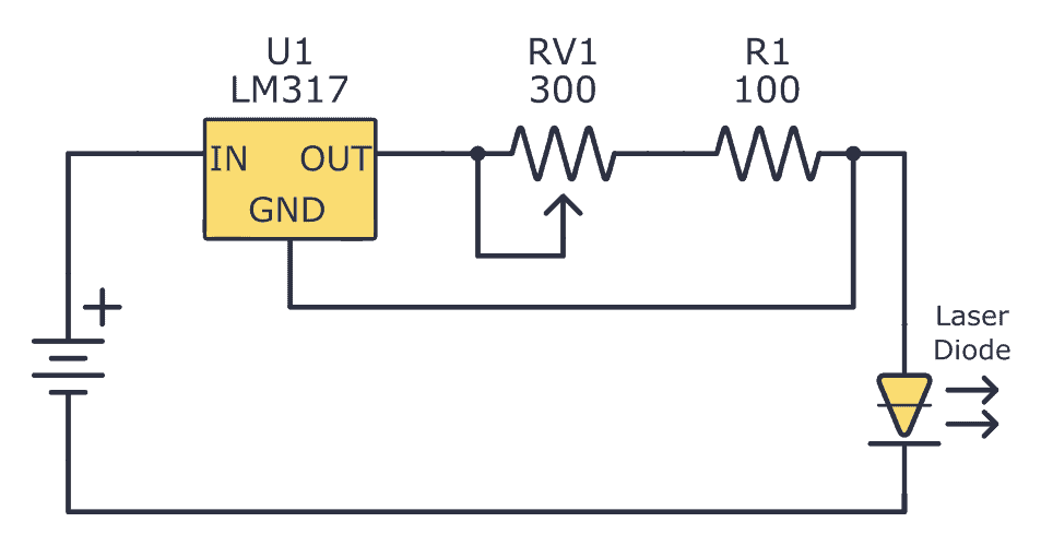
Wiring Example #1: Potentiometer as a Simple Variable Resistor
If you need a simple resistor that you can change the resistance of, you only need two pins: the middle pin and one of the side pins.
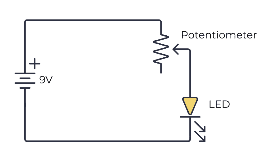
The above image shows a simple circuit to dim a Light-Emitting Diode (LED). In a real circuit, you might want to add an extra resistor in series to make sure you don’t destroy the LED even if you adjust all the way to one side so that the resistance becomes zero.
Turn the shaft in one direction and the resistance increases so that the LED becomes dimmer. Turn it in the other direction and the resistance decreases and the LED becomes brighter.
Wiring Example #2: Connecting the Third Pin to the Middle
Sometimes you’ll see circuit diagrams where the middle and bottom pins are connected to the same point. Why?
This way of connecting is actually equal to using only two pins. Connecting the third pin to the middle pin does not affect the resistance at all.
So why do it?
Some people prefer it this way because they feel it’s a bit messy having an unconnected pin, so they connect it like this. It also makes the circuit diagram a little bit nicer-looking I think.
Wiring Example #3: Potentiometer as Volume Control
This example uses all three pins of the potentiometer to create a simple way of adjusting the volume of an audio amplifier.

By connecting it like this, you’ll get a voltage divider that decreases the voltage of the input signal. The more you turn the shaft, the more you decrease the volume.
This wiring is very common in audio equipment.
More Electronic Components Tutorials

Get Our Basic Electronic Components Guide
Learn how the basic electronic components work so that circuit diagrams will start making sense to you.
I like your explanation their so east to understand thank u very much
I’m glad you like it!
Really interested in electronics and enjoy the mail you send me. Like to expand my knowledge as much as possible. Look forward to the next mail. Thanks David.
Great to hear!
Oyvind
How to increase the value of potentiometer for example from 500 Ohm to 2k Ohm?
Thank you
Sorry, I mean from 500k Ohm to 2 M Ohm
I’m not sure if I understand you. You can buy 2M potentiometers if you need that.
And you can turn the knob of the potentiometer so that it gives you 500k, or 2M.
Oyvind
can this potentiometer be also used to regulate the buzzer frequency in an alarm system?
Yes it can!
Thank u so much my dear mr.Nydal dahl for inspiring me as far as electronics is concerns and to be honest u are a blessing to the world from GOD.. May our GOD bless u dear and please keep on sending me mails. Thanks alot.
I’m glad you find it useful =)
Thanks Oyvind that’s such a good of you to give such explanations. I will soon be ordering potentiometers so I am extremely glad too have these explanations and circuits
Glad I can help =)
I want to build a collective for helicopter simulation control, with USB input.
Can I buy a potentiometer that is limited to say 45 or 50 degrees of rotation?
If not, will it still work if I limit the rotation with stops, or is there not enough current in that range of rotation for it work correctly?
Hi,
The lowest rotation I have seen on a potentiometer is 120 degrees. But yes, you can limit the rotation with stops.
Best,
Oyvind
Thanks so much for this.
l hope a potentiometer could also be used as a voltage selector when building a charger?
Hi Regent,
Yes it can. For examplem, check out the lm317 by googling “lm317 variable power supply”
Best,
Oyvind
OK , thanks.
1.what is the Y symbol?
2.where are the two terminals of the audio input?
…last question
3.do u connect all the three pins of the potentiometer? if so, which to which?
I’ll be looking forward to your reply thank you
Hi,
1) What Y symbol?
2) Do you mean for Wiring Example #3: Volume Input? “In Right” is one and ground is the other.
3) See examples in this article
Hi, your page is super helpful, thank you!
I am wiring up a guitar:
http://www.guitartechcraig.com/techwire/tech04.jpg
The potentiometer digrams look like they have four connections: 3 pins and one mysterious connection to the center. Can you help me decode it?
Thank you!!
Hey Denny,
The mysterious connection at the center just means that you should connect a wire to the metal body of the potentiometer. This is often done in guitars to reduce noise.
Best,
Oyvind
It’s a ground wire
Good tutorial,
In example #2, I believe the reason the third pin is connected to the middle pin is just in case the wiper fails, then at least you would still have resistance instead of an open circuit.
That makes sense!
like your explanation could I use this to make the fueltank sender and the fuel gauge a bit more accurate ?? what value of potentiometer
I managed to fry a couple of potentiometers. Can you give me a few caveats on how NOT to do this?
Potentiometers have a max watt rating. Often 0.25W. If you turn your potentiometer all the way to one side and end up with for example 1 Ohm of resistance, then you can have maximum 0.5V voltage drop over it. This is easily achieved with a resistor in series.
Hi
I have a potentiometer with 4 pins. Please advise what the fourth pin is for
Could be just a connection to the housing for grounding purposes. Or if it’s a clickable potentiometer it could have to do with the switch.
Dear sir,
How should I wire a dual taper potentiometer? Where is position of grounds?
Regards
Chandran
Dual taper is just two potentiometer that use the same shaft. There is no “ground” pin, so I’m not sure how to respond to that question.
Best,
Oyvind
how to connect 4 gang potentiometer for frequency changing type.
how to connect potentiometer to ARM processor.
I have a force dryer for my dog grooming shop, the motor takes a very long time to stop, the techs say I need to send it in to set potentiometer, can I turn the shaft myself to remedy this problem, if so which way do I turn it?
I have a USB fan that I would like to vary the speed of. If I cut and strip the USB wire, which wire do I connect the potentiometer to?
If the fan is using the 5V directly from USB, you can connect it between the 5V and the ground wire.
I would like to reverse the rotation of the potentiometer knob on my golf power caddy, is it just a question of swopping the two outside leads on the three terminal potentiometer.
Yes, that’s the norm. But if you want to be 100% sure you can measure the resistance between the two pins. If it does not change when you turn the knob, then those are the ones to swap.
Hi I’m thinking of running a 240v 3000watt heating element with a potentiometer that I’m thinking of getting off of an old cook stove. Does that make sense ? Will it work?
Yes, as long as your potentiometer can handle the power.
Just had a new potentiometer put on my cart. Now I have to press the accellator nearly to the floor to make it go. Is the part not put in, or set, right?
Hi
I really loved your site. It’s so informative giving explanations about resistors , ohms law and much more. Makes the concepts for beginners very understandable. The best part being the community where one every one is willing to help each other understand the concepts.
I am repairing the volume control of my speaker creative 4.1 4400. Turns out the potentiometer its controller uses is a B50k 50 Ohms 5 pins . I understand that the three pins are potentiometer pins and other two must be switch. To find a fix I searched the web and came across a blog with a quick fix
http://itnews-solutions-tips.blogspot.com/2016/02/a-quick-fix-for-creative-inspire-41.html?m=1
I got the fix alright but I wanted to understand how the person calculated to a 10k 5 pin potentiometer for a B50k potentiometer. I understand there are resistors of 24k and 4.7k In series’s for the middle pin and 1.5k and 2.7k for the led . But I don’t understand how he is calculating to downgrade a B50k potentiometer for a 10k potentiometer .
Also if you could explain how two extra pins for the switch work in the potentiometer as I couldn’t find any tear downs for the mechanical working of the 5 pin potentiometer. I wanted to understand the calculation part.
Hi Ashish,
I don’t know why he switched it for a 10k. Maybe it was just because he didn’t find a 50k one.
If it’s a potentiometer with a switch, those two extra pins are most probably the two pins for the switch that are either connected or disconnected depending on the switch state.
Hi,
I was searching why some people connect 3 pins in the resistance scenario instead of 2 pins, and you give the right information .
So thank you for that
So leg one is the one when the resistans is zero with the wiper turned all the way to the left?
If the wiper is turned all the way to the left, the resistance between the left leg and the center leg will be zero, yes.
Very nice site! I think even I almost got it now :-D
Hi,
Thanks for your articles about electronics, they come really useful when trying to understand things in a less mathematical and more intuitive way… I have a doubt though?
All the volume controls I have seen in audio circuitry do use scenario 3 with the 3 pins to get that voltage divider and thus affect the volume… I have also seen how for pitch changes (meaning affecting voltage) like circuit bending it’s usually scenario 2 connecting just 2 pins and acting as a pure variable resistor.
Now the question is, if in the diagram u show for scenario 3 I did NOT connect pin 3 to ground, acting then as in scenario 2 (only 2 pins connected) a voltage drop will still occur, and the amount of the voltage drop will depend on the variable resistor right? Would this not act as a volume knob too? If not, can you please explain why?
This also brings me to another question, what affects the volume, current or voltage? Both right, since they are directly proportional?
Because for instance in a portable speaker with a given battery usage rated at a given mAh, and they give you a working time before the battery needs recharging, for instance 8 hours, I guess it’s measured at “normal” volume, since at max volume all the working time, the time would rapidly decrease right?
Sorry for the long description but it’s something I keep on asking to myself and thought it could be a nice time to come with a final answer ;)
Hope I can get your reply sometime soon, please keep up doing what you do with this website, it helps thinking about elevtronics as simple as possible and you do a great job with that!
Best!
Yes, a voltage drop would still occur if you only connect two of the pins in scenario 3. But you’d get a voltage divider between that resistance and the internal resistance (or impedance) of the amplifier input.
But if you use all three pins of the pot, you have the full range of the input signal from 0 to max.
I’m not sure I agree with your sentence “Connecting the third pin to the middle pin does not affect the resistance at all” in example 2. Yes, that is correct for the “zero” position, but for anything else, you’d have to consider the circuit as two resistors in series with a tap (wiper) in the middle, whereas if the third leg of the potentiometer wasn’t connected, then it’d be a circuit with just one resistor. I agree that the difference is completely negligible and doesn’t apply to any practical circuit, but theoretically, if you actually put in numbers in a formula, they’re not the same.
You have two resistors in series, yes. But there is a wire from the upper side of resistor 2 (from the wiper) down to the lower wire of resistor 2. So you have a wire in parallel to the lower resistor. And the resistance of a wire (0 ohm) in parallel with any resistor is still 0 ohm. That means only the resistance of the upper resistor matters.
Thank you Sir, that was helpful and straight to the point.
Hi
I want to use a 12vlt 17amp atx psu as a bench supply and would like to use a potentiometer to give me a variable supply other than the 3,3,5 and 12volt.
Can I use a 2k pot to achieve this safely?
Hello Admin great article. I found 5kohm potentiometer used with a 2kohm thermistor. Surely a 5kohm thermistor would be recommended to make the system operate the way its supposed to.
Hi can i move the restricter on my pot to make my mobility scooter go a bit faster thank you
Hey I have a Thunderbolt 305 cb amp and can’t find what to replace potentiometer with. Number on it are 1376745. 69300-6 if any one knows I would greatly appreciate it. Thanks
I have a lathe that I have fitted with a industrial sewing machine motor but want to change the foot pedal to a potentiometer someone has given me a wiring diagram how to do it but I have three questions before I attempt to do it , 1st does it matter what way round it’s connected IE the two out side pins, 2nd he said make sure it’s earthed , it’s going in a cast metal box so I presume box to motor is that correct , 3rd diagram shows 3K3 1/2 W on one wire what is that.
On an electric bike with manual potentionometer that goes to a 24 volt motor, can the 24 volt power (red wire), be attached to the wire of the potensiometer and make the motor spin at different RPMs. , or will the 24 volt wire fry the wire coming from the potensiometer. Don