The rectifier diode lets you convert alternating current (AC) to direct current (DC). In this guide, you are going to learn how this component works and some of the circuits you create by using one.
Diodes are one of the basic electronic components in electronics. There are many types of diodes, but the most common one is probably the rectifier diode. It allows current to flow in only one direction and by connecting it a certain way, you can convert AC to DC.
The rectifier diode is made just like any other normal diode, but instead of being designed for small currents, it’s designed for large currents and voltages. This makes it ideal to use in power supplies.
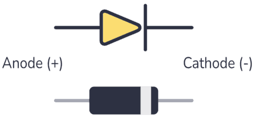
The diode symbol is made up of a triangle pointing to a straight line. The triangle represents the direction the current can flow through the diode. For example, in the picture above, the current can move to the right. But it can’t flow the other way.

How to Use a Rectifier Diode
Rectifier diodes allow current to flow in only one direction, from anode to cathode, also called Forward Bias. The rectifier diode in forward bias is made by connecting the anode to the most positive side and the cathode to the most negative side. You can see this in the example below:

In the above picture, the diode is forward-biased, which means that current can flow through it and the LED will light up. When you use a rectifier diode in this way, it acts similar to a closed switch that allows current to flow through the circuit.
What happens if you reverse the connection of the diode, like this?

When the positive terminal of the power supply is with the cathode and the negative terminal with the anode, the diode is Reverse Biased. With this type of polarization, current can’t flow through the rectifier diode, therefore the LED won’t light up in the above circuit.

10 Simple Steps to Learn Electronics
Electronics is easy when you know what to focus on and what to ignore. Learn what "the basics" really is and how to learn it fast.
What is a Half-Wave Rectifier?
In the examples above, the rectifier diode circuits used a DC power supply, which means a voltage with a fixed value. However, when this diode is connected to an AC power supply, that is where the “rectifying” property comes into play.
An AC power supply provides voltage in periodic oscillations rather than a constant value, with a positive half-cycle and a negative half-cycle, like so:

This kind of voltage is what you find in the outlets in your home. Yet, when you look at most of the electronics in your home, like your phone or laptop, you’ll find they need DC voltage to function. This is why you need rectifier diodes; they help you convert AC into DC.
Converting from AC to DC with a Rectifier Diode
The most significant step in converting AC into DC is the rectifying process, which means that it makes the negative half-cycles disappear. The simplest way to do this is with the following half-wave rectifier circuit:

Only one diode is required to construct a half-wave rectifier. During the positive half-cycle of the AC voltage, the diode is forward-biased and the current can flow through the diode. In the negative half-cycle of the AC voltage, the diode is reverse-biased and the flow of current is blocked.
What you get from this circuit is a final output that is simply the positive half-cycle waveform.
What is a Full-Wave Rectifier?
When you only get the positive voltage values with a half-wave rectifier, the negative half-cycle gets wasted. The solution to this problem is a full-wave rectifier, which lets the positive half-cycle flow and converts the negative half-cycles into positives.
In the devices you use, full-wave rectifiers are what are most commonly used to convert AC voltage to DC voltage.
A full-wave rectifier circuit made with diodes is called a diode bridge. Check out the diode bridge in the circuit below:

The diode bridge consists of four diodes – D1, D2, D3, and D4 – that are connected together. You can see how D1 and D3 share the same cathode, while D4 and D2 are connected by the anode. At the same time, the cathode of D4 is attached to the anode of D1, and the cathode of D2 is placed in the anode of D3.
The Positive Half-Cycle
During the positive half-cycle of the power supply, diodes D1 and D2 can conduct, while diodes D3 and D4 cannot because they are reverse-biased. With this arrangement, the positive half-cycle gives you a current that flows through the circuit, like so:

The Negative Half-cycle
During the negative half-cycle, diodes D3 and D4 conduct, while diodes D1 and D2 do not. Even though the circuit now receives the negative half-cycle, you can see in the picture below how the current flows through the load (output) in the same direction as before. That’s how this circuit turns the negative half-cycles into positives.

What are Some Common Rectifier Diodes?
When you need to choose a rectifier diode, you have to consider some characteristics, for example:
- Peak reverse voltage: this is the maximum voltage the diode can withstand in reverse bias before breakdown.
- Maximum forward current: the maximum value of the forward current that the diode can carry without damaging the device.
- Peak surge current: the maximum current surge that a diode can handle for a short period of time.
- Maximum voltage drop: this is the voltage that stays in the diode when it is forward-biased. Commonly, it will be 0.7v for diodes made of silicon.
The following table contains a list of the most common rectifier diodes and their characteristics.
| Diode name | Peak reverse voltage | Max. forward current | Peak surge current | Max voltage drop |
|---|---|---|---|---|
| 1N4001 | 50 | 1 A | 30 A | 1.1 |
| 1N4002 | 100 | 1 A | 30 A | 1.1 |
| 1N4003 | 200 | 1 A | 30 A | 1.1 |
| 1N4004 | 400 | 1 A | 30 A | 1.1 |
| 1N4007 | 1000 | 1 A | 30 A | 1.1 |
| 1N5402 | 200 | 3 A | 200 A | 1.2 |
| 1N5406 | 600 | 3 A | 200 A | 1.2 |
| 1N5408 | 1000 | 3 A | 200 A | 1.2 |
Questions?
Do you have any questions about rectifier diodes or any feedback you want to share? Let me know in the comments below!
More Diodes Tutorials
10 Simple Steps to Learn Electronics
Electronics is easy when you know what to focus on and what to ignore. Learn what "the basics" really is and how to learn it fast.

This was a fantastic explanation of a diode rectifier. As a mechanical engineer who likes to build vacuum tube amplifiers, I need explanations I can understand intuitively, and this did the trick.
If you could ever do an explanation of how stereo amplifier output transformers are matched to speaker impedance that would be awesome! I just cannot get a handle on that.