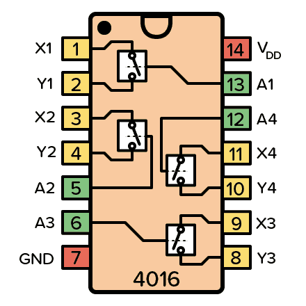
The CD4016 is a CMOS IC with four analog switches, which can be controlled individually using a control pin. The signal can flow in either direction between the two pins of each switch.
Each switch has an enable pin (A) and two input/output pins (X and Y). When the enable pin is set to HIGH, current can flow between X and Y in either direction. However, when enable is LOW, no current can flow between the pins. Just like a switch.
Pin Overview
| Pin Name | Pin # | Type | Description |
|---|---|---|---|
| VDD | 14 | Power | Supply Voltage (+3 to +15V) |
| GND | 7 | Power | Ground (0V) |
| A1-A4 | 5,6,12,13 | Input | Enable pins for the four bilateral switches |
| X1-X4 | 1,3,9,11 | Input/Output | Pin X for each switch |
| Y1-Y4 | 2,4,8,10 | Input/Output | Pin Y for each switch |
What is an analog switch?
An analog switch is a circuit that behaves like a relay, but without any moving parts.
Each switch is made of two MOSFET transistors. And it works with both analog and digital signals in either direction (bi-directional).
The switch can be opened or closed using an enable pin. When HIGH, the MOSFET switch closes so that current can flow. When the enable is set LOW the MOSFET switch opens so that current cannot flow. The 4016 IC has four of these switches.
How To Use The 4016 IC
First of all, you need to connect the VDD pin (pin 14) to your positive supply terminal and GND pin (pin 7) to your negative supply terminal. You can use a power supply voltage between 3V and 15V. Although, some versions of the 4016 chip support up to 20V. Check your datasheet for exact values.
The CD4016 IC has four bilateral switches that you can control by setting a pin HIGH or LOW. Since they are bidirectional, you can choose which pin (Y or X) you want to use as your input and output.
CD4016 Example Circuit
Setting up a circuit with the 4016 is very simple.

Build Something Useful This Evening
This gadget lets you use any IR remote-control to control your lamp, garden lights, heater oven, garage door, or anything else.
Below is a practical example that you can build with the CD4016. It’s a circuit that lets you test one of the switches in the chip.
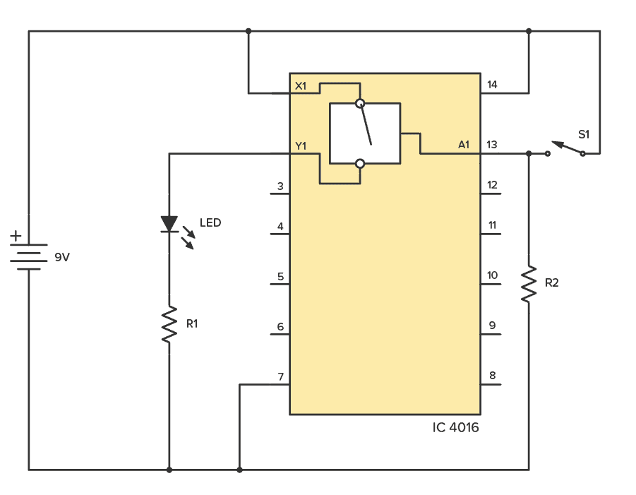
To build this circuit you’ll need:
- IC 4016, such as the CD4016BE
- Light-Emitting Diode (LED)
- A resistor of around 500-1000 Ω (R1)
- A resistor of around 10k-100k Ω (R2)
- Mechanical Switch (S1)
Whenever you close the mechanical switch S1, the analog switch of CD4016 will also close and the LED will light up. You can reverse the connection and the LED will still light since it is a bidirectional switch.
Alternatives and Equivalents for CD4016
You likely find the IC 4016 marked as CD4016, NTE4016, MC14016, HCF4016, TC4016, or HEF4016. Usually with a few extra characters at the end (Ex: CD4016BE).
This has to do with the manufacturer of the chip and the technology used. But the functionality and the pins are the same.
If you can’t find any of these chips in your local electronics store, check out my list of online stores with several options to buy from.
You could try one of the following IC alternatives with analog switch functionality:
- CD4066: Quad analog switch (low “ON” resistance)
CD4016 Datasheet
Download the PDF datasheet for the IC 4016 here:
CD4016B (Texas Instruments)
HEF4016B (Nexperia)
Go back to the full overview of the 4000-series integrated circuits

10 Simple Steps to Learn Electronics
Electronics is easy when you know what to focus on and what to ignore. Learn what "the basics" really is and how to learn it fast.