A DC linear power supply is an electric circuit that converts AC voltage to a stable regulated DC voltage – without any switching or digital circuitry. This makes the circuit both simple to understand and easy to build.
In this guide, you will learn how DC linear power supplies work and how to build your own.
What Does a Linear Power Supply Do?
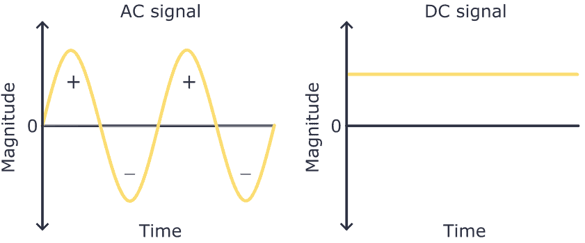
A linear power supply converts AC into DC and gives you a stable DC voltage output. So first, you need to understand the difference between AC and DC voltage:
AC voltage changes its polarity and magnitude periodically, whereas DC voltage is stable and remains constant in polarity.
Here’s a simple comparison between AC and DC voltage signals:
Electrical outlets in your wall provide AC voltage. But most devices, like your phone or laptop, need DC voltage to work.
That’s why chargers or DC wall adapters exist; they convert AC voltage to DC and lower the voltage, allowing you to power up your device from any electrical wall outlet. These wall adapters are small power supplies.
To build a linear power supply, you’ll need the following components:

10 Simple Steps to Learn Electronics
Electronics is easy when you know what to focus on and what to ignore. Learn what "the basics" really is and how to learn it fast.
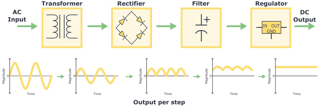
- Transformer: The AC voltage from the wall outlet has a high magnitude, like 110/220 V AC. So the first thing to do is transform it into a signal with a lower magnitude. This is achieved using a component called a transformer.
- Rectifier: Once the AC voltage is transformed, it is then passed through a rectifier. The rectifier converts the AC voltage into pulsating DC voltage by allowing current flow in only one direction and removing the negative portion of the AC waveform.
- Filter: After rectifying, a filter is used to smooth out and minimize the pulsating DC voltage. Typically, due to their ability to store energy, capacitors are used in this kind of filter circuit.
- Regulator: To have a stable DC voltage value output, a voltage regulator is needed. It ensures a constant and stable DC voltage output, compensating for fluctuations in the load or input voltage.
Transformer
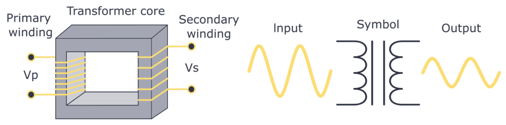
A transformer is a component that consists of two coils with wire wound around a magnetic core. When an AC current flows through the primary winding, it creates a changing magnetic field, which induces a current in the secondary winding. The number of wire turns in each winding determines the attenuation or amplification factor. For example, you could convert 110 V AC into 12 V AC by choosing the right transformer.
Take a look at the construction and symbol of a transformer:
Rectifier
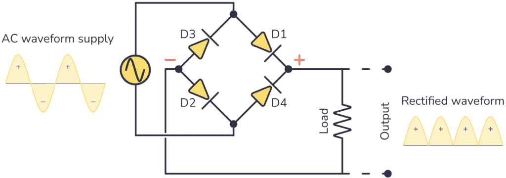
The rectifying step is a key part of converting AC to DC. It uses rectifier diodes to eliminate the negative half-cycles of the AC signal.
The most common setup of these diodes is the diode bridge. Below you can see how the diode bridge circuit converts the AC signal to only positive cycles:
Capacitor filter
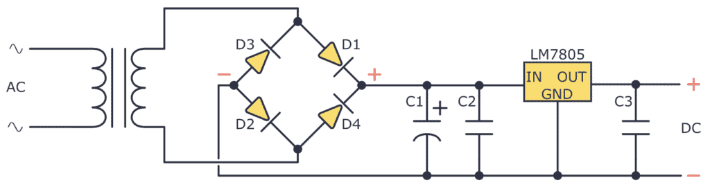
Once you get a pulsating DC signal from the rectifier you can smooth it by implementing a capacitor as a filter. To build this filter you just need to connect a capacitor between the positive and negative terminals you get from the diode bridge.
The capacitor will charge as the rectified voltage increases and release its charge as the rectified voltage decreases. Observe this behavior below.
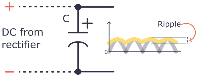
You can see how even if a filter is applied, the AC signal is not 100% steady, it still has some small magnitude variations. This effect is called ripple. The higher the capacitor capacitance, the lower the ripple.
Voltage Regulator
Once you get the DC voltage there are many ways to regulate it to a desired value. For example, you can use a Zener diode, or you could implement a dedicated voltage regulator circuit such as devices from the LM78xx family.
Let’s suppose you want to regulate the voltage that comes after the capacitor filter to 5V, for that using the LM78xx family you’ll need the LM7805.
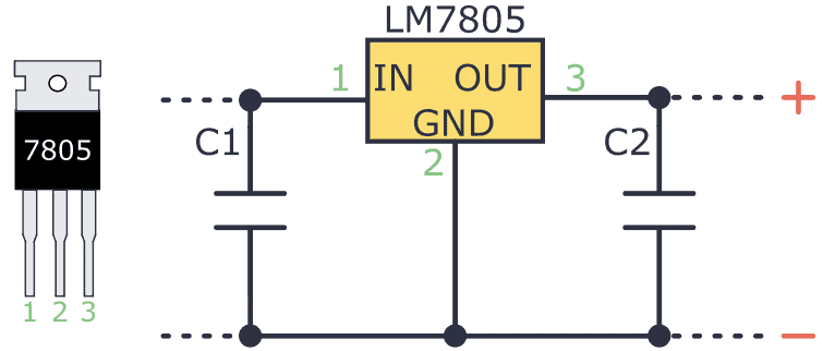
As you can see this voltage regulator is very easy to use. It typically has an input pin (Vin), an output pin (Vout), and a ground pin (GND). The input pin must be attached to the positive terminal of the input voltage to regulate, while the output pin goes to the load. The ground pin must be connected to the circuit’s common ground.
Also, I recommend adding capacitors to the input and output pins to reduce ripple and noise.
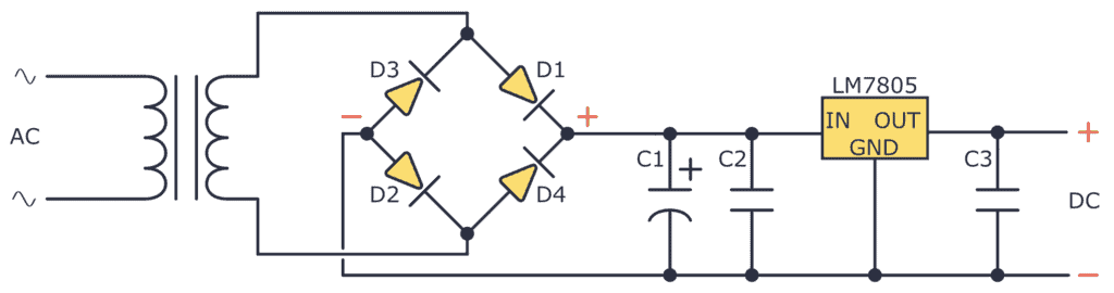
Put all this together, and you’ll end up with this circuit:
Building a DC Linear Power Supply
Now that you know how a DC linear power supply works, it’s time to see how you can build one!
Step 1: Wire the Transformer
The first thing to do is wire the transformer. I have 127V AC in my wall outlet, so I used a transformer designed for this. The one I used was a center tap transformer 127 V AC / 18 V AC.
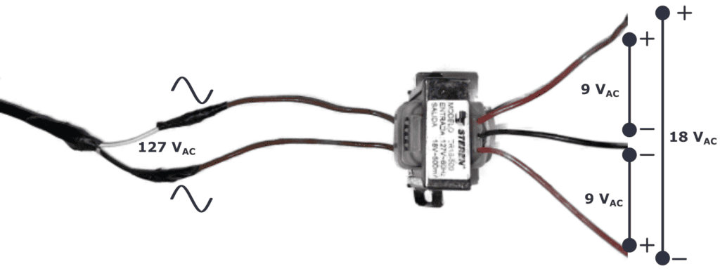
A center tap transformer has a secondary winding with a center tap in the middle. This design allows multiple voltage levels from a single transformer configuration. For example, to get +9V, 0V, and -9V.
For this circuit, I only used one of the 9V AC outputs.
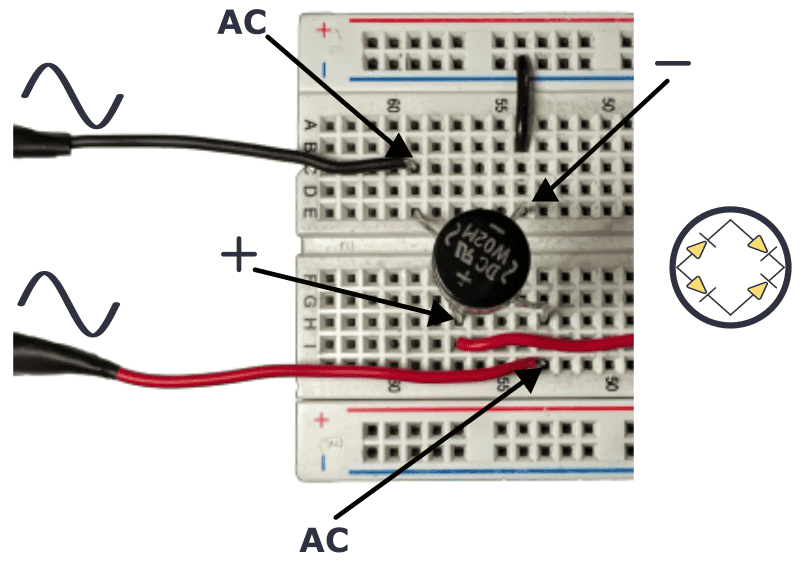
Step 2: Add a Diode Bridge
For the rectifier, I used the diode bridge W02M, which has the necessary diode arrangement within its compact body.
This device has four terminals, two for receiving the AC voltage and two for outputting the pulsating DC signal. See its connection below.
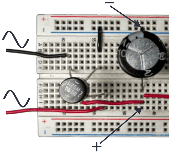
Step 3: Filter the Rectified Voltage With a Capacitor
To smooth out the pulsating DC voltage, you already know you need to use a simple electrolytic capacitor. For this example, I used a 1000 uF capacitor. Check out its wiring:
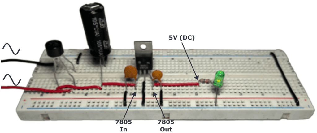
Step 4: Regulate the DC voltage
At this point, the output voltage of the 1000 uF capacitor is 9 V DC. To regulate the voltage to 5 V this example uses the LM7805 regulator.
The LM7805 datasheet recommends placing two ceramic capacitors at the input and output terminals of 0.33uF and 0.1uF respectively.
Also, you can see how a green LED was connected to the 5V output just to illustrate how this DC linear power supply works.
Questions
Do you have any questions about the DC Linear power supply or any feedback you want to share? Let me know in the comment field below!
More Power Supplies Tutorials

Get Our Basic Electronic Components Guide
Learn how the basic electronic components work so that circuit diagrams will start making sense to you.