Yes, basic electronics is easy. As long as you don’t make it complicated (which many unfortunately do).
An electrical current is the flow of electrons in a wire. Electrons flow when you have a “closed loop” – a path from the negative to the positive terminal of a battery.

For example, if you connect a small light bulb to the positive and the negative side of a battery, you will get a closed loop where electrons can flow and make the lamp shine.
“Electronics” control electrical currents by combining different components.
What is Basic Electronics?
Many think that basic electronics has to do with the physics of how electrons move. But that’s particle physics, not electronics!
You can learn the basics of electronics by learning this:
- The basics of current and voltage
- How the most common basic components work
- How electronic schematics work
- How to build circuits from schematics
The Basics of Current and Voltage
The biggest misunderstanding about electric current is that current can be “used up”. Current is never “used up”! The current flowing out of the battery is exactly the same as the current flowing back into the battery!
Check out our article What Is Electric Current? to learn more.

Get Our Basic Electronic Components Guide
Learn how the basic electronic components work so that circuit diagrams will start making sense to you.
As for voltage, it’s important to know that voltage is always measured between two points. Yes, sometimes we say that the voltage at this point is X, but it’s always implied that it’s compared to a reference, such as the minus terminal of the battery.
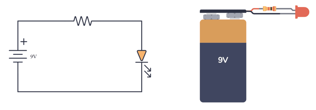
The second point about voltage is that the applied voltage to a circuit is always the same as the sum of the voltage drops. So if you have a circuit with a 9V battery that connects to a resistor and a Light-Emitting Diode (LED), and you know that the voltage across the LED is 2V, then the remaining 7V WILL drop across the resistor.
If you know this about current and voltage, then you know the basics. This is the basis of Kirchhoff’s Laws of Voltage and Current.
Basic Electronics Components
There are many basic electronic components available to enable different types of functions in your circuit.
Three of the most important components are the resistor, the transistor, and the capacitor.
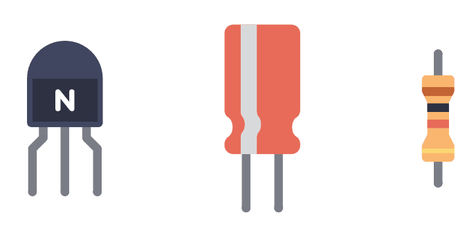
A resistor doesn’t “do” anything actively. But you use it to set the right current or voltage level.
With a transistor, you can amplify your signal, invert your signal, or lots of other stuff. Transistors make up logic gates which make up all digital electronics such as a processor in a computer.
Capacitors are like tiny batteries. They are often used to introduce time delays into a circuit.
Practice building simple circuits with all the basic electronic components, and learn how voltages and current behave with them. Then you have this step nailed down.
How Schematic Diagrams Work
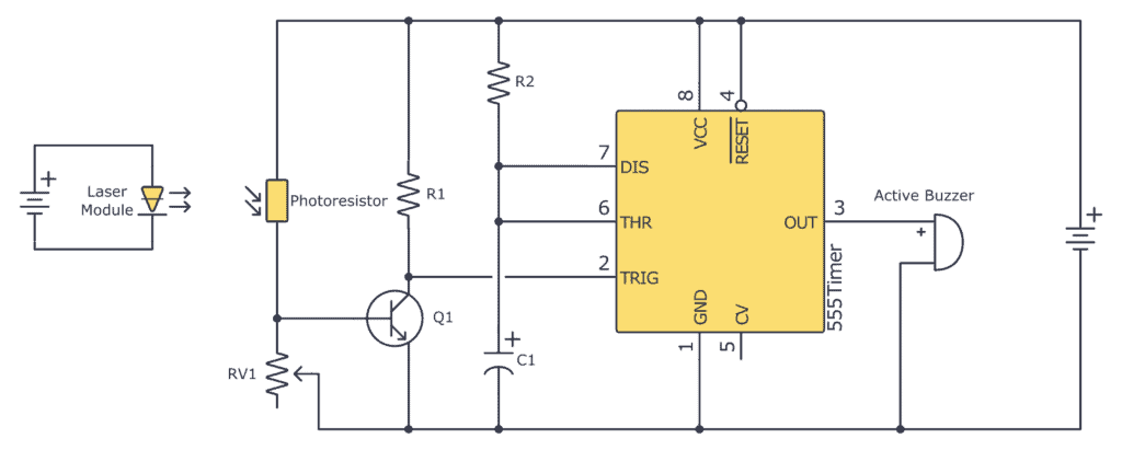
To make any electronic circuit, you start with a schematic diagram. A schematic is a drawing of a circuit. It tells you which components are needed and how to connect these components.
You can either design your own schematics or find free schematics available online.
The lines between the components tell where you need to make connections to build this circuit. Here’s a quick video about how schematics work:
Understanding and Designing Your Own Schematics
To understand what a specific schematic does, and eventually be able to design your own, it’s good to expand your knowledge with additional electronics theory.
You should at least know how to work with series and parallel circuits.
And it’s really useful to know the basic electronics formulas:
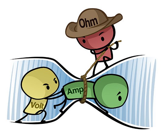
- Ohm’s law
- The Voltage Divider
- Kirchhoff’s Current Law and Voltage Law
- Thevenin’s Theorem (although I rarely use this one)
Knowing this will let you do things like calculate resistor values for different parts of your circuit, simplify complicated circuits, and be able to “see” what a circuit does much quicker, without doing a lot of analysis.
How to Build Circuits From Schematics
To build a circuit from a schematic, you have to create the same connections that are on the schematic in real life. You can do this with wires, using a breadboard, a perfboard, a stripboard, or create your own printed circuit board.
The first step to getting started building circuits is to get a breadboard and just build lots of circuits on it for practice. It’s a lot of fun, and it helps a lot in understanding circuits as well.
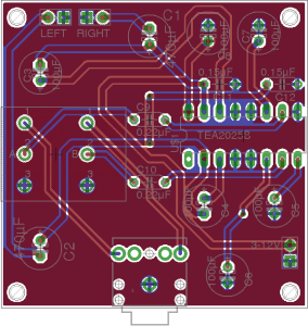
Designing Your Own Circuit Boards
From the schematics, you can also design a printed circuit board if you want. You do this by drawing the wires from the schematics and placeholders for the different components.
Then you create your circuit board by one of the following methods:
- Manufacturer
- Etching
- CNC milling
When your circuit board is created, you solder your components onto the board. Voila! Your electronic circuit is complete.
Basic Electronics Summary
In this guide, I’ve covered the essentials of basic electronics, and it comes down to:
- Understanding current and voltage.
- Understanding key components like resistors, transistors, and capacitors.
- Knowing how to read and design schematic diagrams.
- Knowing how to build circuits from schematics.
By focusing on these concepts and practicing building circuits, you’ll quickly build a good foundation in electronics. And you’ll be ready to begin designing and building your own electronic projects in no time!
More Basic Electronics Tutorials
Get Our Basic Electronic Components Guide
Learn how the basic electronic components work so that circuit diagrams will start making sense to you.
