Open Collector Output – What Is It and How Do I Use It?

An open collector output is not a normal high/low output. Instead, these outputs are connected via a transistor. And the collector of the transistor is available at the pin. For example, if you have a NAND gate with an open-collector output, it will look like this: So when the output from the NAND gate is ‘1’,

Beginner’s Guide to the Shift Register in Digital Electronics

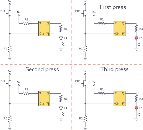
A shift register is a common building block in digital electronics that is used to store and move bits, for example, to convert from serial to parallel data and vice versa. 

How a shift register work
How bits move through a shift register

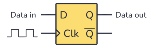
It is basically a group of flip-flops that can store bits, and shift its stored bits sideways by one bit-position every time it is triggered. It is made using a series of D flip-flops with the output of one connected to the input of the next. Each clock pulse triggers a shift. 

In this tutorial, you will learn the different types of shift registers, how they work, and how to build them using flip-flops.

The T Flip-Flop (Quickstart Tutorial)

The T Flip-Flop is a flip-flop that can toggle its output. Toggling means switching its output to its opposite; 1 becomes 0, and 0 becomes 1. This type of flip-flop is often used in counters and frequency dividers. In this quickstart tutorial, you will learn how it works, its truth table, and how to build

The JK Flip-Flop (Quickstart Tutorial)

The JK Flip-Flop is a type of flip-flop that can be set, reset, and toggled. It can be used for making counters, event detectors, frequency dividers, and much more. In this tutorial, you will learn how it works, its truth table, and how to build one with logic gates. What is a JK Flip-Flop? Flip-flops

The D Flip-Flop (Quickstart Tutorial)

The D Flip Flop is an edge-triggered circuit that combines a pair of D latches to store one bit. It is commonly used as a basic building block in digital electronics to create counters or memory blocks such as shift registers. In this tutorial, you will learn how it works, its truth table, and how to build one with logic gates.

The D Latch (Quickstart Tutorial)

The D Latch is a logic circuit most frequently used for storing data in digital systems. It is based on the S-R latch, but it doesn’t have an “undefined” or “invalid” state problem. In this tutorial, you will learn how it works, its truth table, and how to build one with logic gates.

Full Adder Circuit – How it Works

A Full Adder is a digital circuit that performs the addition of three binary inputs. In this tutorial, you will learn how this circuit works, its truth table, and how to implement one using logic gates.

Schematic for a Full Adder Circuit
A Full Adder Circuit

What is a Full Adder?

Adders can either be Half Adders or Full Adders. The difference is that the Half Adder is used to add only two 1-bit binary numbers, therefore its sum can only range from 0 to 2. To improve this performance, the Full Adder was developed. It is able to add three 1-bit binary numbers, achieving a sum range from 0 to 3, which can be expressed with two output bits (“11”). 

The S-R Latch (Quickstart Tutorial)

The S-R latch is a key circuit in digital storage units. In this tutorial, you will learn how it works, its truth table, and how to build one with different logic gates.

S-R Latch Symbol
S-R Latch Symbol

What is an S-R Latch?

Before starting with the S-R latch you need to know what a latch is. A latch is an asynchronous circuit (it doesn’t require a clock signal to work), and it has two stable states, HIGH (“1”) and LOW (“0”), that can be used for storing binary data. Many sequential circuits and larger storage devices, such as shift registers, use latches as their principal building block.

Half Adder Circuit – How it Works

A Half Adder is a digital circuit that adds binary numbers. In this tutorial, you will learn how it works, its truth table, and how to implement one using logic gates. 

Half Adder Circuit
A Half Adder Circuit

What is a Half Adder?

A Half Adder is a digital circuit that carries out the addition of binary numbers. It’s the simplest of digital adders and you can build one using only two logic gates; an XOR gate and an AND gate.

Binary Number System And Working With Ones And Zeroes

Binary number system - ones and zeroes

The binary number system is an important system in digital electronics. Because in digital electronics we are using only 1’s and 0’s. But what does this mean?

That’s something I was wondering about for a long time. I thought it was something really difficult and abstract. But when I one day asked my dad about it, it really surprised me how easy it was!

It turns out that a “1” is just a wire with voltage and a “0” is a wire without a voltage. It’s that simple!

The reason for this system is to make the electronics easier. A circuit which only needs to check if there is a voltage or not on the wire is really easy. Just have a look at how the transistor works and you’ll get an idea.

In order to make any sense out of the ones and zeroes, we use a binary number system.