Basic Electronic Components Used in Circuits

Some basic electronic components drawn as cartoons

I learned about the basic electronic components by going to the library and reading books.

I was just starting out.

And I felt like a lot of the books explained everything in a difficult way.

In this article, I will give you a simple overview, with an explanation of the basic electronic components – what they are and what they do.

The Most Common Basic Electronic Components

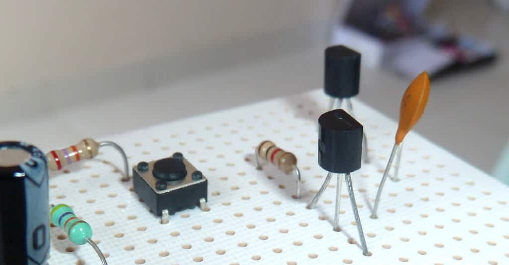
These are the most common components:

  • Resistors
  • Capacitors
  • LEDs
  • Transistors
  • Inductors
  • Integrated Circuits

Resistor

A Through-Hole Resistor
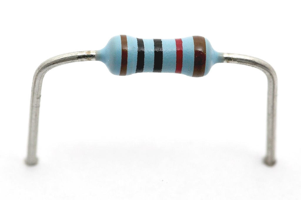
Find the resistor symbol in the schematic symbols overview.

I didn’t understand the resistor in the beginning.

It didn’t seem to do anything! It was just there, consuming power. But with time, I learned that the resistor is actually extremely useful.

You’ll see resistors everywhere. And as the name suggests, they resist the current.

But you are probably wondering: What do I use it for?

You use the resistor to control the voltages and the currents in your circuit.

Some basic electronics components: LED in series with a battery and a resistor

How?

By using Ohm’s law.

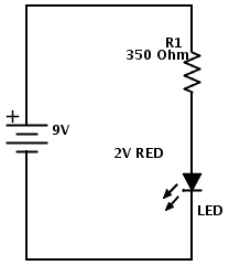
Let’s say you have a 9V battery and you want to turn on a Light-Emitting Diode (LED).

If you connect the battery directly to the LED, LOTS of current will flow through the LED!

Much more than the LED can handle. So the LED will become very hot and burn out after a short amount of time.

But – if you put a resistor in series with the LED, you can control how much current is going through the LED.

In this case, we call it a current-limiting resistor.

It’s also possible to find adjustable/variable resistors. This is called a potentiometer and it has three pins.

Capacitor

Electrolytic capacitor
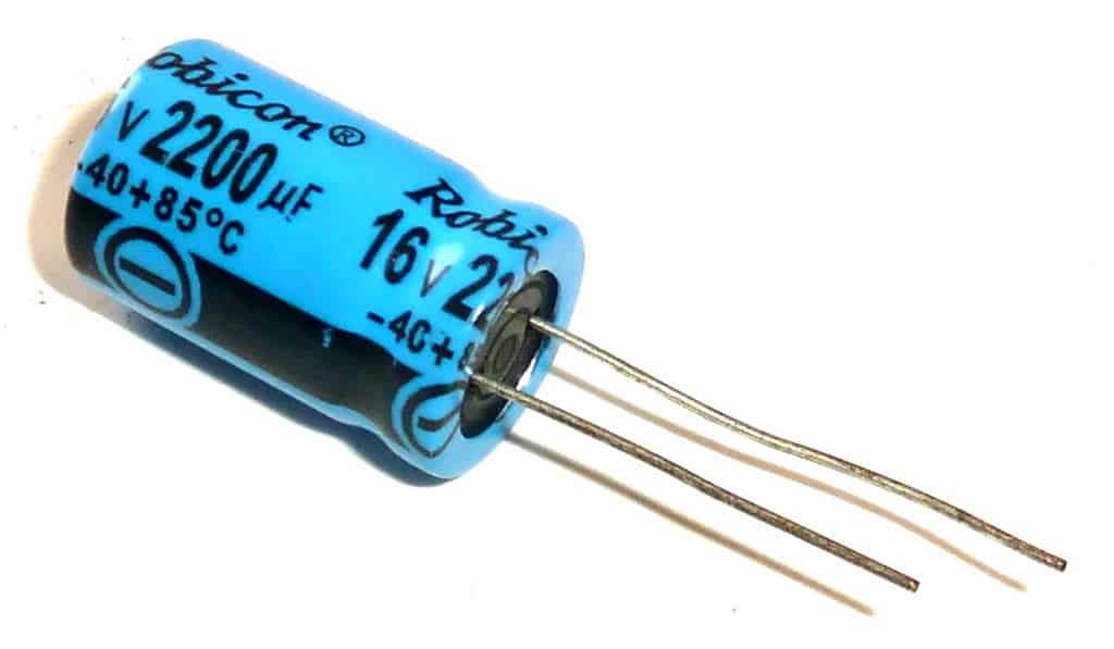
Find the capacitor symbol in the schematic symbols overview.

You can think of a capacitor as a battery with very low capacity.

You can charge and discharge it just like a battery.

The capacitor is often used to introduce a time-delay in a circuit.

For example to blink a light.

It’s commonly used for removing noise, or making the supply voltage of a circuit more stable.

Read more about the capacitor in this article: How Does A Capacitor Work?

There are many capacitor types. Most commonly, we divide them into polarized and non-polarized capacitors.

Light Emitting Diode (LED)

leds-in-a-pile
Find the LED symbol in the schematic symbols overview.

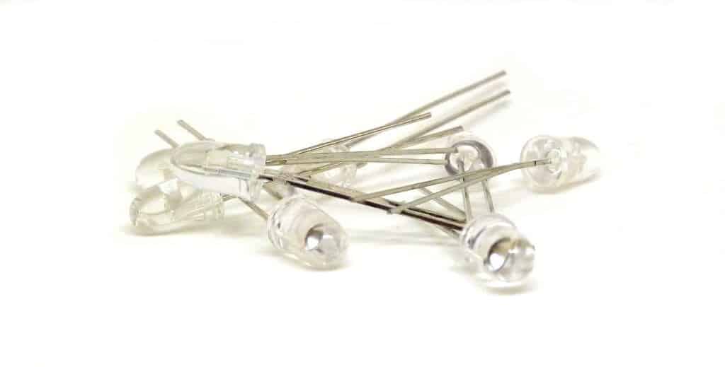
A Light Emitting Diode – or LED for short – is a component that can give light.

We use LEDs to give a visual feedback from our circuit.

For example to show that the circuit has power. But, you can also used them to make cool light-show circuits.

You see these components everywhere:

In your laptop, on your mobile phone, on your camera, in your car +++

And you can find many different types of LEDs.

A very common circuit to build as a beginner is the blinking light circuit.

Transistor

Two transistors in a circuit
Find the transistor symbol in the schematic symbols overview.

This is probably the hardest of the basic electronic components to understand.

But don’t worry, it’s not that hard.

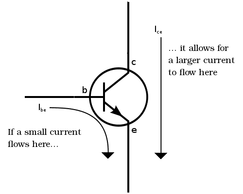
A simple way is to look at the transistor as a switch controlled by an electrical signal.

If you put about 0.7 volts between the base and the emitter, you turn it on.

Note that this is true for NPN transistors. There are also other types, but worry about these later.

But, instead of having just two states (ON or OFF), it can also be “a bit on” by controlling the current that goes through its base.

A bit of current on the base produces a current of maybe 100 times more (depending on the transistor) through the Collector and Emitter. We can use this effect to build amplifiers.

Explanation of how a transistor works

I’ve previously made a video on how transistors work.

Inductor

A homemade inductor
Find the inductor symbol in the schematic symbols overview.

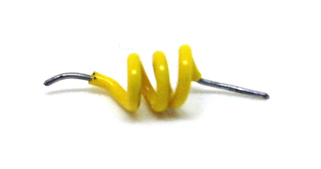
Inductors are a bit weird.

It’s just a coil of wire – and you can make one yourself by making some loops out of a wire.

Sometimes they’re wound around a metal core of some sort.

They are often used to make radio oscillators, more efficient power supplies, and filters.

It’s not that often that I used one actually, but in my article What is an inductor? you can see how it works with some nice animations.
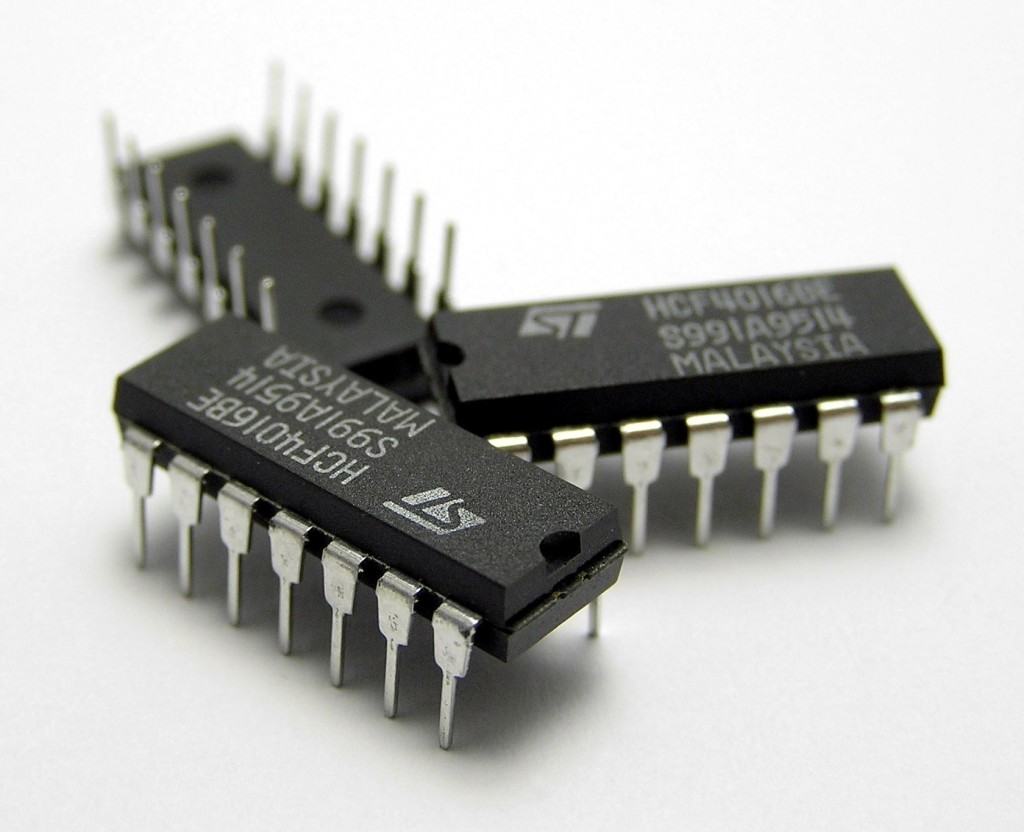
Integrated Circuit

Integrated circuit - one of the basic electronic components
Find the integrated circuit symbol in the schematic symbols overview.

An Integrated Circuit (IC) consists of many basic electronic components.

It’s nothing mysterious or magical.

It’s just an electronic circuit that has been shrunk to fit inside a chip.

It could be an amplifier, it could be a microprocessor, it could be a USB to serial converter… It could be anything!

To figure out what a specific IC does, you can read its datasheet.

What to do next?

Now, you know a bit about the basic electronic components.

But don’t just read about it – take action and start building electronics:

Ohmify is an online academy for electronics. Learn to build your ideas with electronics, even if you have no experience from before. It includes a community forum where you can ask questions about what you are learning or if you’re stuck on your on project.

Click here to learn more about Ohmify.

Do you understand the basic electronic components? Leave your comment or questions in the comment field below!

More Electronic Components Tutorials

182 thoughts on “Basic Electronic Components Used in Circuits”

  1. Hi am karthick
    I am recently joined in a laptop service center
    I don’t know much about electronic
    I just know little bit. If u tell me guide me or give me some tips
    That how can I troubleshoot the mother bird problem like no power , when connect the Adaptor to the laptop the goes off and how to trace out the some failure or short component in mother boards. If u can help this

    Reply
  2. So a transistor is like a switch that i can put in halfway down a power wire for like an LED and turn it on from somewhere else with a switch that powers the transistor. And then transistor will turn the LED on and off by controlling the power flow into it. Have i got that right?

    Reply
  3. Awesome simple language to clear basis concepts of electronic components.
    Huge thanks Oyvind Nydal Dahl
    Awaiting eagerly your forthcoming articles

    Reply
  4. Wow I,ve been an art student since, after reading this explanation I just switched to science…… Thank u for dis explanation!!

    Reply
  5. sir, i have to face the electronic competition.. But, i don’t know about electronic.. So, sir, could you please tell me or guid me how to make a simple electronic device…..?

    Reply
  6. Capacitors have been used in many appliances all around the world. From basic appliances like TV sets and microwaves to large satellites in space, capacitors have a function everywhere. Great post! Good that you share your practical knowledge.

    Reply
  7. Øyvind, I am very new to this stuff and you are a great person for making this website so you can freely express your knowledge. I am very thankful that put your time in making these articles for the people who will one day mold the future. Thank you Øyvind!:D

    Reply
  8. Thank you very much, i think you are created to help newbies like me, after getting your e-book getting started with electronics my level is gradually increasing as i’ve started understanding and building simple stuff which makes me never wanting to stop cos i find them exciting alway willing to do more .
    Thanks

    Reply
  9. All the info here are really useful since they are very short and to the point so we can clearly understand.. but can you explain what is a base Material(use in PCBs) and i’m doing a project about PCBs. can you advice me about the things that I have to include in my book?

    Reply
  10. I’m a newbie and always desiring to get more knowledge on electronic, i find this tutorial to be so helpful. And though the turorial is short but it is rich.
    You’re doing a great work here, God bless you.

    Reply
  11. Wow Im so greatful of you making it so under standing for us all GOD gave you this path to teach all your knowledge and for you to pass it on.
    I would say this is one of your paths GOD gave you to share GOD BLESS

    PS. I THANK YOU FOR MAKING MY BRAIN A LOT MORE KNOWLEDGED
    AND I WILL ACCEPT ALL THAT YOU CAN SHARE

    WAYNE WRONA

    Reply
  12. hi sir…
    i really find your tutorial, more intresting. kudos.. thats so great jst keep it up..
    actually i will be starting my project work and i hope for your assistance.
    thank you.

    Reply
  13. Hi bro thanks for this, am learning. please I like to download 10 Steps To Learn To Build Electronics, but it not download as I clicked on the download button…

    Reply
    • Hey, just follow the instructions and you should get to the download. If you get an error message, please let me know.

      Best,
      Oyvind

      Reply
  14. Good day to you, I am trying to repair a PCB but am finding it difficult to procure the resistor that has blown. The resistor has specific coloured bands on it. Any suggestions on how to identify the manufacturer of this specific resistor?

    Reply
  15. I really hands off you not for the simple and easy explanation of the components of the but for the labour you did for finding all these informations in a simple way……..
    Thank you very much………

    Reply
  16. You did a really good job explaining the parts of a circuit. I’m sure that I read similar books to you in the beginning and it always took me reading the information two or three times before it really sank in. I just wanted to learn how circuit boards worked and it didn’t take long to get in over my head. Your explanation is much better for a beginner and I feel like the books would have made much more sense if I had read this first.

    Reply
  17. Thanks man. Really helped me for my science olympiad. I am 10 and will turn 11 on may 9th 2017. I’m doing circuit design for the science olympiad so this really helped. :)

    Reply
  18. Normally i purchase leds from led123.ca/en but i could not know how to build a led circuit board at home if you have some knowledge so you can share with because your this blog really helpful those who want to learn more about electricity

    Reply
    • I have made some DIYs before and last time it was a speaker with the led light. You should try more, it was not very difficult as long as you have the right introduction and all tools on hand.

      Reply
  19. I’m one of the newbies and I must confess that i’ve learnt alot from your teachings As there are always very easy and simply to comprehend. Thanks!

    Reply
  20. hi i m pramod kr. pandey
    n i m jst completed my plytchnic in 2013
    but no given to me a chance to expressed in this line electronics
    plz gv a sujjesto how to improve in my life in the line of electronic ;

    Reply
  21. Thank you for typing this up. I am trying to build a robot like baymax from Big Hero 6 by hand and looking up things used in computers, microchips, and codes that will help me in this case. I am willing to make it learn two languages and to do things like this, I need to know the basics and this article helps me understand what I need and how to use it.

    Reply
  22. This is some really good information about circuit boards. I liked that you pointed out that LEDs can be a really great visual feedback. It is good to know that a can help you figure out if it is working properly.

    Reply
  23. Dear, i am confused about what you have written about resistor. I think when we connect a resistor in series with the led the current will remain same because in series current remain same but voltage divides so i think in this case the resistor act as a voltage limiting resistor.

    Reply
    • Hi,

      A LED without the resistor in series will have a lot of current flowing through it. Let’s say 100 mA for the sake of the explanation. But if you add a 330 Ohm resistor in series with it, the current is 21mA.

      The current is the same in the LED and in the resistor yes, but if you compare the circuit with and without a resistor – you’ll see that a resistor in series limits the current.

      Best,
      Oyvind

      Reply
  24. Hi. I’m having a difficult time finding your “Getting started with electronics” book in South Africa☹️Is the book available this side?

    Reply
  25. Shout out to Øyvind! This blog post has stood the test of time, hasn’t it?

    Wanted to bump an earlier comment from the summer of ’15 by Hugh Simpson (if that is your real name), turning me on to Fritzing (fritzing.org). Awesome software and community!

    Thanks Øyvind, keep up the good work!

    Reply
  26. good morning please i am new in this field and i have passion for this …I realii want to know how to get started…how to connect components in a dash board

    Reply
  27. Hey now,
    I have a box fan that stopped working. I tore it apart and found 1 electronic component, Besides the copper wire and the metal it was wrapped around.The component looks like a black box with a couple wires coming out of it. Can you tell me what this little black box is and what it does in relation to the workings of the fan? I actually have like 5 fans and they all have the same black box and all 5 don’t work. Could you help me understand what these boxes are all about? Some yahoo told me that they are capacitors, and that they help the fan start spinning, but if thats the case, why when I help the fan start spinning with my hand, they still don’t work. Whats up with that? By the way,your site is my goto electronics site when im confused.It helps me understand what the parts are and what they do, but my brain is confused when i look at all the parts, and i seem to instantly forget what they do, maybe some electric field fried my brain,but most likely…..I’m just stupid. Love the site and thank you from the bottom of my heart, nobody else is trying to teach people about this stuff in a way that’s understandable to the non electrician .
    Sincerely, skin

    Reply
  28. Great article, i have read all your articles. I am working at allchips limited from last month, i want learn more. Our website is electronic components supply chain, but no explain of them…

    Reply
  29. PLEASE sir, i want to build a mobile charger circuit diagram 100-220v AC circuits DIY i have gotten the diagram but i don’t know the value of the components that i will use please help me on that. it’s samuel

    Reply
  30. This is a great blog site for electronics hoviets, about the components used under the basics electronics and electronics sector, have been explained in detail in detail in this blag series, which is quite beneficial for those interested in electronics. Thanks

    Reply
  31. The way you explain flees my fears about electronics and inspires my passion to learn even more until I overflow with knowledge to share with technological knowledge based LOVE . . . . . . . .

    Reply
  32. Such an interactive tutorial. Thank you so much for putting in your thoughts. I am sure it will help many. Great work :)

    Reply
  33. I’m a US Navy Veteran aircraft electrician with an Associates degree in Electronics Technology. I worked with high frequency electronics in the defense industry until I became disabled with Lupus.

    With all that experience, I must say your descriptions and methods of teaching are the best I’ve ever seen. Ohmify will help me teach some really cool stuff to my grandkids. Thank you!

    Reply
  34. So I got into circuits because I was wanting to make more advanced Energy Constructs and “functional sigils” for Magick. funny how many of these symbols go back to Norse Galdrstafr and carry similar meanings, for instance the symbol for antennae and aerial antennae are the same as in bindrunes, and is for sending and receiving information/energy, capacitors have same symbols, also the symbol for allowing energy to pass but not back flow are all the same… so I have come to the conclusion that the 1st Master Electrician was also a Master Magickian.

    Reply

Leave a Comment