The CD4060 is a CMOS chip with a binary counter and oscillator included. It can be used to produce selectable time delays or to create signals of different frequencies. This is because it has a built-in oscillator module that only requires a few passive electronic components.
From only two resistors and one capacitor it can create 10 different frequencies . That makes it a very interesting chip, especially for those interested in audio and synthesizers.
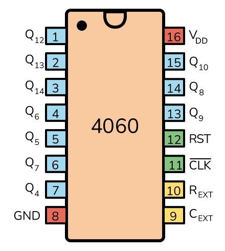
Pin Overview
| Pin Name | Pin # | Type | Description |
|---|---|---|---|
| VDD | 16 | Power | Supply Voltage (+3 to +15V) |
| GND | 8 | Power | Ground (0V) |
| Q4-Q10 * | 1-7 | Output | Counter outputs |
| Q12-Q14 * | 13-15 | Output | Counter outputs |
| CEXT | 9 | Input | Connection for external capacitor |
| REXT | 10 | Input | Connection for external resistor |
| CLK | 11 | Input | Clock input/Oscillator pin |
| RST | 12 | Input | Resets the counter |
* Note that the datasheet for HEF4060 uses the names Q3-Q9 and Q11-Q13 instead.
What is a Binary Counter with Oscillator?
A binary ripple counter is a circuit made up of D flip-flops in series. The output of one is connected to the CLK input of the next. The CLK input of the flip-flop on the left is the counter input.
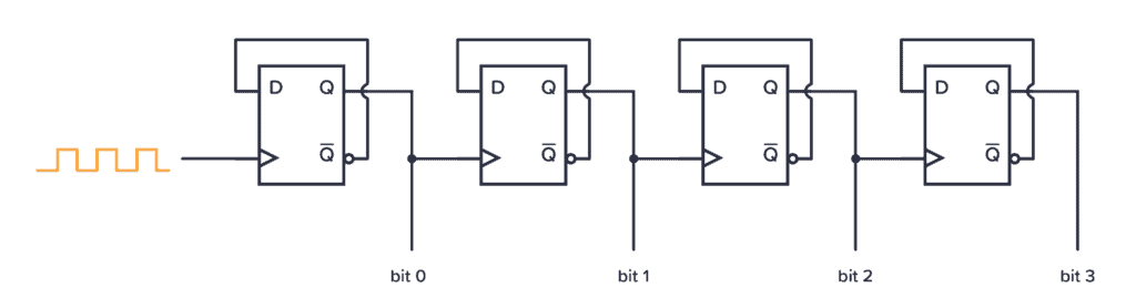
Instead of just four flip-flops like in the example above, the CD4060 has 14 flip-flops in series. This means it can count up to 16383 (the maximum value of 14 bits).
It also has a built-in oscillator that makes it possible to create a clock pulse to automatically increase the counter. This makes the CD4060 a timer circuit that can be used to select between different time delays (or frequencies), depending on which Q-output you use.
For example, if you choose values for the resistor and capacitor so that the oscillator creates a clock pulse of 1 Hz, it means it will increase the counter every second. So for an 8-second delay, you can use output Q4. Or for a delay of 2 hours and 16 minutes (8192 seconds), you can use output Q14.
The Missing Outputs Q0, Q1, Q2, Q3, Q11
For some reason, the CD4060 lacks the outputs Q0 to Q3 and Q11. I’ve been told that the input pulse is counted as Q0 (does not apply for HEF4060).

Build Something Useful This Evening
This gadget lets you use any IR remote-control to control your lamp, garden lights, heater oven, garage door, or anything else.
But what about Q1 to Q3 and Q11?
I haven’t found any official info on why those outputs are omitted, but the most probable theory I’ve read is that the 4060 is an upgrade of the 4040. The 4040 had 16 pins, so they might have removed some of the bits to be able to add an oscillator and a higher bit count with the same amount of pins.
How To Use The CD4060
First of all, you need to connect the VDD pin to your positive supply terminal and the GND pin to your negative supply terminal. You can use a power supply voltage between 3V and 15V. Although, some versions of the 4060 chip support up to 20V. Check your datasheet for exact values.
To activate the oscillator, connect a resistor from the REXT pin, a capacitor from the CEXT pin, and a resistor from the CLK pin, and connect all three of them at the other end:
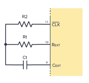
The frequency is given by this formula:
Frequency f (Hz) = 1 / ( 2.3 * Ct * Rt )
Note that Rt needs to be much lower than R2 for the formula to be correct.
If you want to reset the counter back to zero, use pull the RST (Reset) pin HIGH. Normally, you need to pull this LOW for the chip to work.
Use any of the Q pins as your output to control whatever you want to control. They become HIGH after:
- Q4 goes HIGH after 23 = 8 clock pulses
- Q5 goes HIGH after 24 = 16 clock pulses
- Q6 goes HIGH after 25 = 32 clock pulses
- Q7 goes HIGH after 26 = 64 clock pulses
- Q8 goes HIGH after 27 = 128 clock pulses
- Q9 goes HIGH after 28 = 256 clock pulses
- Q10 goes HIGH after 29 = 512 clock pulses
- Q12 goes HIGH after 211 = 2048 clock pulses
- Q13 goes HIGH after 212 = 4096 clock pulses
- Q14 goes HIGH after 213 = 8192 clock pulses
Using a Crystal with the CD4060
Want to use a crystal for better precision?
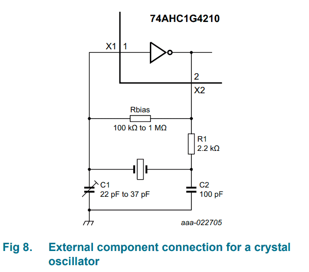
That’s possible. This type of oscillator is called a Pierce Oscillator.
The datasheet of the CD4060 does not say much about how to choose values for this. But I found a similar chip, the 74AHC1G4210. It works like the 4060, except that it only has one output instead of several.
It gives a bit more info in its datasheet:
A typical crystal oscillator schematic is shown in Figure 8. R1 is the power limiting resistor, its value depends on the frequency and required stability against changes in VCC or average ICC. For starting and maintaining oscillation a minimum transconductance is necessary, so R1 should not be too large. A practical value for R1 is 2.2 kΩ.
What Crystal To Choose?
Let’s say you want to use the 4060 IC as a frequency divider to get 500 Hz. What crystal do you need?
Q4 needs 8 clock pulses to go from low to high. And another 8 to go from high back to low again. So it needs 16 pulses for one complete cycle (frequency period).
It’s the same for every output, so we can use this to find the theoretical crystal frequency you’d need to get 500 Hz from a given output:
- For Q4 output, you’d need a crystal of 500 * 16 = 8 kHz
- For Q5 output, you’d need a crystal of 500 * 32 = 16 kHz
- For Q6 output, you’d need a crystal of 500 * 64 = 32 kHz
- For Q7 output, you’d need a crystal of 500 * 128 = 64 kHz
- For Q8 output, you’d need a crystal of 500 * 256 = 128 kHz
- For Q9 output, you’d need a crystal of 500 * 512 = 256 kHz
- For Q10 output, you’d need a crystal of 500 * 1024 = 512 kHz
- For Q12 output, you’d need a crystal of 500 * 4096 = 2.048 MHz
- For Q13 output, you’d need a crystal of 500 * 8192 = 4.096 MHz
- For Q14 output, you’d need a crystal of 500 * 16384 = 8.192 MHz
Not all these exist as crystal values, it’s just an example of how you can find viable crystal frequencies for a given output. But the 2.048MHz or 4.096MHz are both pretty common and will give you 500 Hz.
CD4060 Example Circuit – Adjustable Timer
Here’s a practical example that you can build with the 4060 chip:
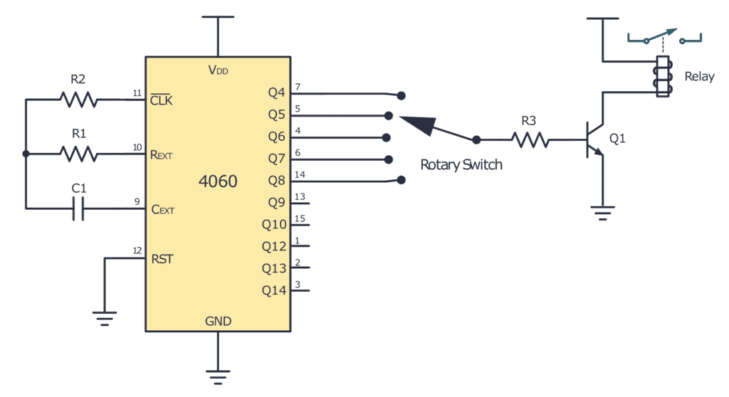
To build this circuit you’ll need:
- A 4060 chip, such as the CD4060BE
- A rotary switch with as many positions as you’d like timer options
- A 100 kΩ resistor (R1)
- 0.22 µF (C1)
- A 1 MΩ resistor (R2)
- An NPN transistor (Q1)
- A 1kΩ resistor (R3) to limit the current through the transistor
- A relay
With the chosen values for C1 and R1, you get a frequency of:
Frequency f (Hz) = 1 / ( 2.3 * 0.00000022 F * 100000 Ω) = 19.8 Hz
So we have about 20 clock pulses per second. And we can thereby find the time delay before each output goes high:
- Q4 goes HIGH after 23 = 8 clock pulses = 0.4 seconds
- Q5 goes HIGH after 24 = 16 clock pulses = 0.8 seconds
- Q6 goes HIGH after 25 = 32 clock pulses = 1.6 seconds
- Q7 goes HIGH after 26 = 64 clock pulses = 3.2 seconds
- Q8 goes HIGH after 27 = 128 clock pulses = 6.4 seconds
- Q9 goes HIGH after 28 = 256 clock pulses = 12.8 seconds
- Q10 goes HIGH after 29 = 512 clock pulses = 25.6 seconds
- Q12 goes HIGH after 211 = 2048 clock pulses = 1 minutes and 42 seconds
- Q13 goes HIGH after 212 = 4096 clock pulses = 3 minutes and 25 seconds
- Q14 goes HIGH after 213 = 8192 clock pulses = 6 minutes and 50 seconds
Alternatives and Equivalents for 4060
You likely find the 4060 IC marked as CD4060, NTE4060, MC14060, HCF4060, TC4060, or HEF4060. Usually with a few extra characters at the end (Ex: CD4060BE).
This has to do with the manufacturer of the chip and the technology used. But the functionality and the pins are the same.
If you can’t find any of these chips in your local electronics store, check out my list of online stores with several options to buy from.
If you can’t find the 4060, you could try one of the following IC alternatives with binary ripple counter. But note that you’d have to create the oscillator yourself:
- 4020: 14-stage binary ripple counter (No oscillator)
- 4024: 7-stage binary ripple counter (No oscillator)
- 4040: 12-stage binary ripple counter (No oscillator)
4060 Datasheet
Download the PDF datasheet for the IC 4060 here:
CD4060B (Texas Instruments)
HEF4060B (Nexperia)
Go back to the full overview of the 4000-series integrated circuits
Build Something Useful This Evening
This gadget lets you use any IR remote-control to control your lamp, garden lights, heater oven, garage door, or anything else.

Excellent article, thank you. I have been looking for a decent article on this chip for months. Here’s my project that uses this chip: https://hackaday.io/project/176063-hackaday-clock-a-day-entry-cmos-logic-clock
Cool project! And I’m glad to hear you liked this article!
I have built a crystal controlled CD4060 circuit to produce a 200Hz output but would ideally like a 500Hz output also. Presumably because of the fixed dividing function of the CD4060 I would not be able to achieve this using a single crystal.
My question is what crystal frequency would I need to produce 500Hz or is there any other way I could use the CD4060 to produce both frequencies?
Hi Paul,
You’re right, you won’t be able to get both frequencies from one crystal on this chip.
In theory, there are 10 different crystals you could use to get 500 Hz:
For Q3 output, you’d need a crystal of 500 * 16 = 8 kHz
For Q4 output, you’d need a crystal of 500 * 32 = 16 kHz
For Q5 output, you’d need a crystal of 500 * 64 = 32 kHz
For Q6 output, you’d need a crystal of 500 * 128 = 64 kHz
For Q7 output, you’d need a crystal of 500 * 256 = 128 kHz
For Q8 output, you’d need a crystal of 500 * 512 = 256 kHz
For Q9 output, you’d need a crystal of 500 * 1024 = 512 kHz
For Q11 output, you’d need a crystal of 500 * 4096 = 2.048 MHz
For Q12 output, you’d need a crystal of 500 * 8192 = 4.096 MHz
For Q13 output, you’d need a crystal of 500 * 16384 = 8.192 MHz
Not all these exists, it was just an example of how you can find viable crystal frequencies for a given output. But the 2.048MHz or 4.096MHz are both pretty common and will give you 500 Hz.
I’ve updated the article with this info.
Best,
Oyvind
Paul, merci de votre message. Cependant je me demande qui vous a demandé votre avis ? personne. alors la prochaine tu ferme ta chatte.
Useful but there’s an error in your f calculation. You specify C1 as 0.22nf but used 2.2uf (0.0000022) in the equation. If you had used C1 as planned then f= 19.76kHz.
Also in the line above you mean C1 and R1 not R2.
You are right. I’ve updated the article. Thanks!
C1 is specified as .22 uF (not nF).
If we go by the values stated, the calculation would be 0.00000022 F * 1000000 Ω, not 0.0000022 F * 100000 Ω – same result but wrong expressions.
Hi, do you have any ideas how to connect a low-voltage frequency source to 4060?
Thanks!
Hi, if you have a clock source, then you can connect that directly to the clock pin on pin 11. And you can leave pin 9 and 10 unconnected.
Hi,
For testing opamps I thought it would be interesting to use this ic to produce a nice range of frequencies, but wasn’t aware that it does not have Q0-Q2 outputs, spoiling much of my plan.
Is there a 4060-like ic with those outputs, or should I just accept that I need to use an extra ic to make an external oscillator and use the 4040?
Can I use a 74HC-series ic to make this oscillator, or would the “1”‘s of too low voltage?
Thanks for your advice.
(BTW I was planning to use a 4MHz crystal.)
There’s no 4060-like IC with Q0-Q2 outputs that I know of.
But you can use a 74HC IC (just match the voltage of the 4040) to make the oscillator. Or use one of the suggestions from this page: https://www.eleccircuit.com/simple-crystal-oscillator-circuit/
Can you use a 504KHz ceramic resonator? Will it work that low with the caps shown? Or do I need to increase the capacitors? I want to divide by 32 to get 15750 Hz. Thanks.
I have no experience with ceramic resonators. But I had a quick search, and looks like those should have the capacitors integrated (if it’s a three-pin). So I think you should be able to connect like in the crystal example, just without adding capacitors.
Many thanks. Its a 2-pin. Looking at other schematics for it, it needs more capacity like 300pf.
hi
is it possible to connect two 4060 , so you can count binary to a higher number ??
Yes, that should be possible. If you connect the highest bit from the first chip into the clock input of the second. But note that the clock input is inverted, so you should invert the signal before connecting it into CLK if you want to make sure the second chip is updated on rising edge like the first chip.
Is there any 74AHC1G4210 like component with a RST pin for the counter? Thanks in advance.
Look like there are pin differences between manufactures. And this chip is from Nexperia HEF4060, 2021, with no Q10 /1024 or Q14 /16384. But the Texas Instuments version, CD4060, 2003, has no Q3 /8 or Q11 /2048.
The relay winding shown on the diagram should have a protection diode fitted across the winding, anode to positive.
Also, your division table is incorrect. Q14 goes high after 16384 pulses. The datasheet is poorly written and has been replicated without any additional clarification. This IC can be very confusing.
Hi,
I need to get a brief pulse out of Q14, so I guess I need to reset the 4060B to continue and get another pulse out of Q14 for the period I need.
But I also need the Q14 output to trigger an input to a 4017B.
So is some for of simple delay needed to reset the 4060B after triggering the 4017B.
Any ideas on simple delay on the reset pin of a 4060B ?
Regards
Antony
I studied these chips in my 20’s and always found then lacking in my intention to build a simple/cheap counter. It didn’t matter that the readouts were LEDS and the counts were in binary. Now, when I revisit this idea, I decided – why not – build it entirely out of D Flip-flops. This way I can have as many stages as I want.
In a year, there are 32million seconds so 25 stages will suffice. With access to set and reset, all the stages can be isolated/tested. What do you think? I isolate each stage by 2 high valued resistors and short the join to ground so I can inject the output from a much earlier stage. This will definitely reduce the maximum speed but at 1 to 1000 Hz(why? sight and sound – I am part of the instrument), I don’t expect any problem. This is the only way to test all the stages in reasonable time. All the outputs will be inverted and run to another set of LEDs. Everything is read as HEX and a simple program in Free42 will decode HEX to Decimal. The inverted LEDS will serve as a check since human errors are expected. To count faster pulses, several 4017 stages can serve as a prescaler. Of course, a single FPGA can handle everything.
This site in general is always my go-to to get help. thank you guys for your amazing work over here!