The CD4511 is a BCD to 7-segment decoder. It means it takes a number in binary form as an input, then displays this number on a 7-segment display using its outputs.
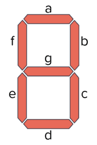
A 7-segment display is a component with seven Light-Emitting Diodes (LED) arranged as shown below. By turning on different combinations of the LEDs, a number between 0 and 9 is displayed.
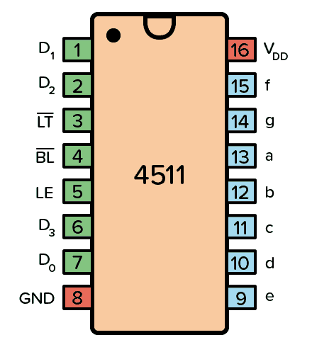
Pin Overview
| Pin Name | Pin # | Type | Description |
|---|---|---|---|
| VDD | 16 | Power | Supply Voltage (+3 to +15V) |
| GND | 8 | Power | Ground (0V) |
| a-f | 9-15 | Output | Outputs for the 7-segment display |
| D0-D3 | 7, 1, 2, 6 | Input | 4-bit data input |
| LT | 3 | Input | Lamp Test. Turns on all segments when LOW. |
| BL | 4 | Input | Blanking Test. Turns off all segments when LOW. |
| LE | 5 | Input | Latch Enable. Stores the current state when HIGH. |
What is a BCD to 7-Segment Driver?
A 7-segment display driver turns on the correct segments of a 7-segment display according to an input.
In this case, the input is Binary-Coded Decimal (BCD). For example, an input of 1001, which is 9 in decimal, would turn on the segments a, b, c, f, and g so that a “9” is displayed on the 7-segment display:

So, how exactly does this IC convert binary codes to decimal numbers? It does so by using a combination of logic gates and D flip-flops.
From the HEX4511B datasheet, we can find the internal circuit of the 4511:
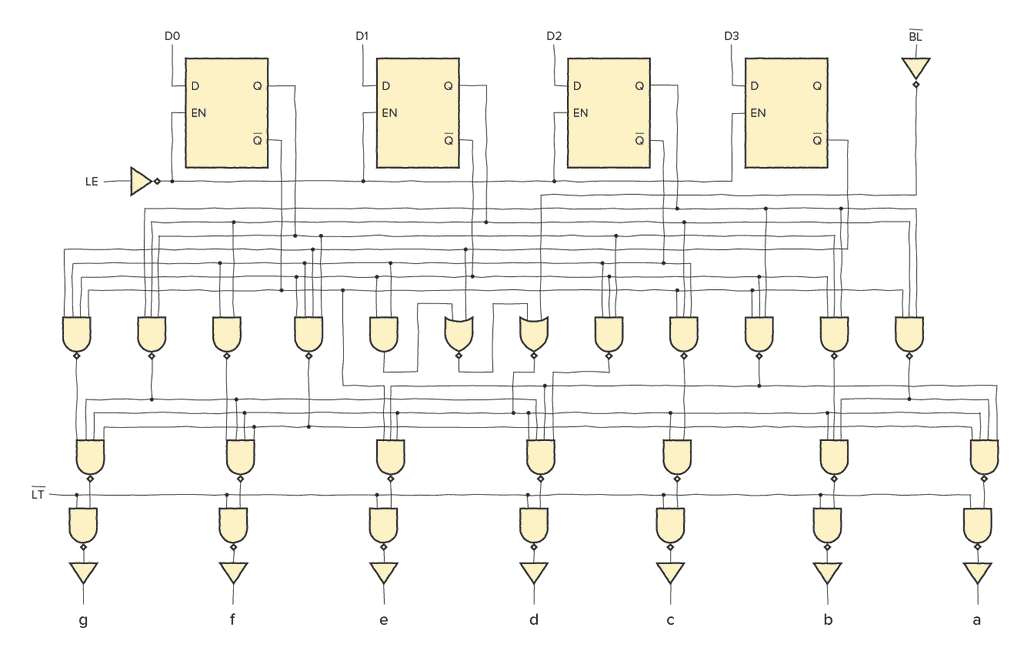
For each input bit (D0-D3), there is a D latch.
When the EN input of a D latch is HIGH, whatever is on the D input is transferred to the Q output. But when EN goes low, the last input value is stored onto the output Q and cannot change.

10 Simple Steps to Learn Electronics
Electronics is easy when you know what to focus on and what to ignore. Learn what "the basics" really is and how to learn it fast.
This means that when LE is LOW, the segment outputs (a to g) are determined by the data on D0 to D3. But when LE goes HIGH, the last data present on D0 to D3 is stored in the latches and the segment outputs stay unchanged.
The logic gates below convert the bits from the latches into 7-segment output.
How To Use the CD4511
To be able to use the BCD to 7-segment decoder in the chip, you need to first connect the VDD pin to the positive supply terminal and the GND pin to the negative supply terminal.
You can use a power supply voltage between 3V and 15V. Although, some versions of the 4511 chip support up to 20V. Check the datasheet of your version of the chip for exact values.
Pins D0, D1, D2, D3 are the BCD inputs through which you feed the number you want to show on the display in binary format.
Pins a to g are the output pins that you connect to your 7-segment display.
The LT (Lamp Test) pin is there to test that all the segments of the display work. Set LOW to test the segments. Set HIGH for normal operation.
The BL (Blanking Test) pin turns off all segments when LOW. You can use it to control the brightness of the display with pulse-width modulation (PWM). Set to HIGH for normal operation.
The LE (Latch Enable) pin, also called store, is used to store the current value. When HIGH, the last data is displayed regardless of the changes to the BCD inputs. Set this pin LOW for normal operation.
CD4511 Example Circuit
Below is an example circuit where you set the input number using switches. The CD4511 controls the 7-segment display so that it turns on the correct segments for displaying the number.
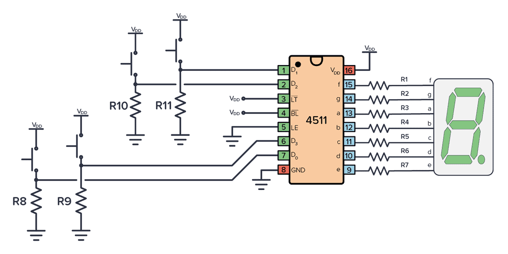
To build this circuit you’ll need:
- A 4511 chip, such as the CD4511BE
- A 7-segment display (Must be common cathode. For example LSHD-5503)
- Seven resistors (R1-R7) of 1kΩ
- Four resistors (R8-R11) of 10kΩ
- Four pushbuttons
This is a fun circuit to build as your first 7-segment display circuit. Later, you can modify the input of this circuit to instead be the output of a counter that counts seconds, to create a stopwatch.
Alternatives and Equivalents for CD4511
You likely find the 4511 IC marked as CD4511, NTE4511, MC14511, HCF4511, TC4511, or HEF4511. Usually with a few extra characters at the end (Ex: CD4511BE).
This has to do with the manufacturer of the chip and the technology used. But the functionality and the pins are the same.
Can’t find any of these in your local electronics store? Then check out my list of online stores where you can find components and tools for all your electronics projects.
Or try one of the following 7-segment decoder alternatives:
- 4026: Decade counter with 7-segment display outputs
- 4054/4055/4056: BCD to 7-segment decoder (for LCD)
- 74HC46/47/48/49: BCD to 7-segment decoder
4511 Datasheet
Download the PDF datasheet for the IC 4511 here:
CD4511B (Texas Instruments)
HEF4511B (Nexperia)
10 Simple Steps to Learn Electronics
Electronics is easy when you know what to focus on and what to ignore. Learn what "the basics" really is and how to learn it fast.