In this tutorial I am going to teach you how to create custom Cadsoft Eagle components.
The part we are creating is a battery holder for a 9V battery from Keystone Electronics. This part is sold by both DigiKey and Farnell, so it is easy to get your hands on.
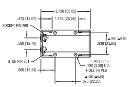
Link to 1294 Battery Holder on DigiKey
To create the component in Eagle we need to:
- Create a symbol
- Create a footprint
- Create a device (Connect the symbol with the footprint)
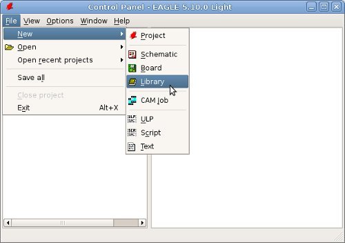
All Eagle components must be created in a library. Start by creating your own custom library. From Eagle’s control panel, click “File -> New -> Library.”
Creating a custom Eagle symbol
To create a new symbol click “Library -> Symbol”. Then write a name for the symbol in the “New” text box and click OK.
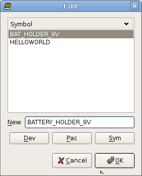
You will be asked if you want to create a new symbol. Click OK.

Get Our Basic Electronic Components Guide
Learn how the basic electronic components work so that circuit diagrams will start making sense to you.
Draw your symbol
We start of by drawing what the symbol should look like.
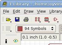
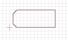
Click on “Draw -> Wire”. Choose the “94 Symbols” layer. This tool lets you draw lines. Draw something that looks like a battery. You decide for yourself how much time and energy you want to put into your drawing. I like to keep it simple.
 |
 |
Add pins/terminals
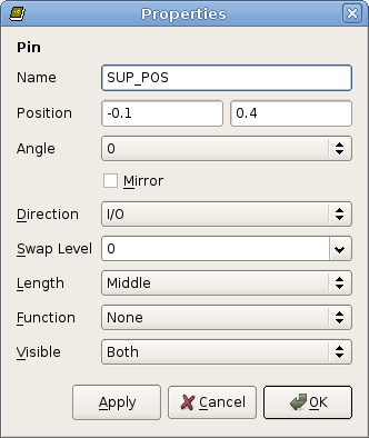
Now, we’ll add pins. Click “Draw -> Pin” and add two pins.
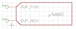
Rename the pins to something more descriptive. For example SUP_POS and SUP_NEG (positive and negative supply). To rename a pin, click “View -> Info”, select the pin and change the “Name” text box.
Add component name
Eagle components should have a name for easy identification.
Click “Draw -> Text”, enter the text “>NAME”, choose the “95 Names” layer and add this to your symbol. This will make the component name show up in the schematics.
If you also want to add the symbol value, you can add the text “>VALUE”. But our battery holder does not need this.
Save your work.
Creating a custom Eagle package
Now we will draw the “footprint” or the “package” of the component. Click “Library -> Package” and enter a name just as we did with the new symbol above.
Component area
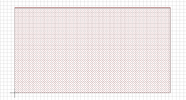
We’ll start by drawing a rectangle that defines the area needed by the component.
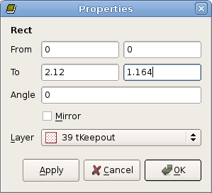
No other components can be placed within this area, so we’ll draw it using the “39 tKeepout” layer.
From the component drawing, we can see that the outer dimensions of the battery holder are 2.120 x 1.164 inches. Draw a rectangle, then open its properties (View -> Info) and set the correct size.
Then draw a line in the “21 tPlace” layer around the component. This will create silkscreen lines on your finished printed circuit board that show where the component is going to be placed.
Pads
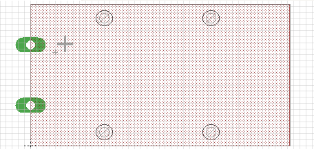
Next, we will draw the two holes with pads for the + and – terminals.
From the drawing, we can see the suggested drill size is 81 mils (2.06 mm) and we can calculate that the negative terminal is placed at X=0 and Y=332 mils and the positive terminal at X=0 and Y=832 mils.
Click on “Draw -> Pad”. Set “Drill” to 0.081 (or 2.06 if using mm). Choose the “Long” pad type. Place two pads on the board.Set the correct positions by using “View -> Info” on the pads.
Set the names to “POS” and “NEG”.
Screw holes
Then we’ll add the four screw holes. From the drawing we find that the drill size is 130 mils. Click on “Draw -> Holes” and set “Drill” to 0.130 inches. Place four holes and then move them to their correct position using “View -> Info”.
Correct positions are:
- X=0.6 Y=0.113
- X=1.475 Y=0.113
- X=0.6 Y=1.051
- X=1.475 Y=1.051
If you would like to add some more info, do this in the “21 tPlace” layer to make it appear as silkscreen on your finished circuit board.
Maybe a plus sign at the positive terminal? Or a “Designed by xxxx” text?
Creating a custom Eagle device
Now, the worst part is over. All that is left to do is to connect the symbol and the package.
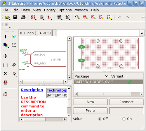
Create a new device by clicking “Library -> Device”.
Choose “Edit -> Add” and add the symbol you have created.
Then click “Edit -> Package” and select the newly created package.
Click “Connect”. Choose the Pins and Pads that are to be connected and click the “Connect” button to connect them. Click OK.
A small green tick is shown in the package window to show that the package has been connected to the symbol.
Save your device.
Summary
You have just made your own custom eagle component. Now you can add this to a schematic design like any other component. If you cannot find it, make sure your library is selected (Click “Library -> Use..”)
Return from Eagle Components to Electronic Components Online

Get Our Basic Electronic Components Guide
Learn how the basic electronic components work so that circuit diagrams will start making sense to you.

