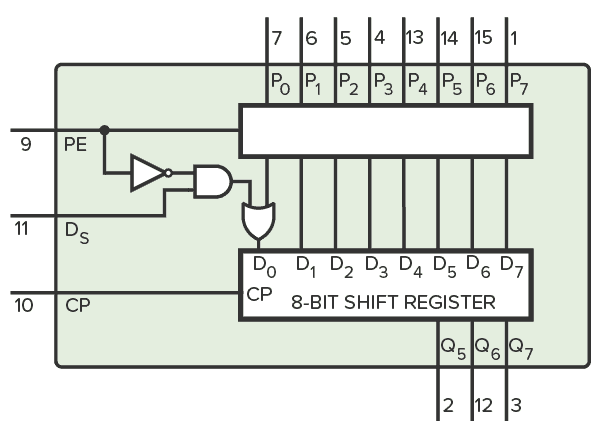
The CD4014 is a CMOS IC that contains a shift register with eight bits. It has one serial input and eight parallel input pins to preload the register. You can use it as a parallel-to-serial converter, for example, to read the state of 8 buttons with only three Arduino pins.
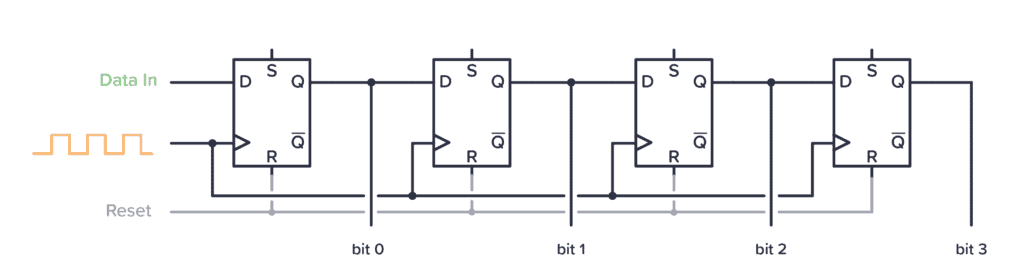
A shift register is a component that is made up of D flip-flops connected in series so that each bit is shifted to the next flip-flop on every clock pulse. Below is a typical 4-bit shift register made from D flip-flops:
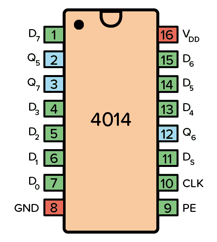
Pin Overview
| Pin Name | Pin # | Type | Description |
|---|---|---|---|
| VDD | 16 | Power | Supply Voltage (+3 to +15V) |
| GND | 8 | Power | Ground (0V) |
| D0-D7 | 1,4,5,6,7,13,14,15 | Input | Parallel data input pins |
| Q5,Q6,Q7 | 2,3,12 | Output | Buffered outputs from the last three bits |
| PE | 9 | Input | Parallel Enable |
| CP | 10 | Input | Clock pin to sync the input |
| Ds | 11 | Input | Serial input pin |
How To Use The 4014 IC
First of all, you need to connect the VDD pin to your positive supply terminal and the GND pin to your negative supply terminal. You can use a power supply voltage between 3V and 15V. Although, some versions of the 4014 chip support up to 20V. Check your datasheet for exact values.
To load data with the parallel inputs, set the Parallel Enable (PE) pin HIGH. Connect your input values to the parallel input pins (D0 – D7). On the next rising clock edge on the CLK pin, the parallel data will be loaded into the shift register.
To shift the data one position, use the CLK pin while keeping the Parallel Enable (PE) pin LOW. In this mode, you can also load data serially via the DS pin.
The CLK pin shifts the data on each rising edge.
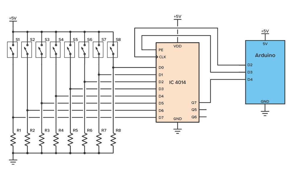
CD4014 Example Circuit
Here’s a practical example that you can build with the CD4014. This circuit lets you read the state of 8 switches by using only three I/O pins on the Arduino:
To build this circuit you’ll need:

10 Simple Steps to Learn Electronics
Electronics is easy when you know what to focus on and what to ignore. Learn what "the basics" really is and how to learn it fast.
- Arduino (or other microcontroller)
- A 4014 chip, such as the CD4014BE
- 8 x Resistors (100 kΩ)
- 8 x Switches
In this circuit, you must create code so that the Arduino first sets D3 HIGH (Parallel Enable) and then provide a rising edge on D2 for the CLK pin. This loads in the current state of all the switches. Now the state of S8 can be read from pin D4.
To read the state of the next switch (S7), provide another rising edge on D2 for the CLK pin. Keep doing this until you’ve read all the eight switches.
Alternatives and Equivalents for CD4014
You likely find the 4014 IC marked as CD4014, NTE4014, MC14014, HCF4014, or HEF4014. Usually with a few extra characters at the end (Ex: CD4014BE).
This has to do with the manufacturer of the chip and the technology used. But the functionality and the pins are the same.
If you can’t find any 4014 chip in your local electronics store, check out my list of online stores or try one of the following IC alternatives that contain an 8-bit shift register:
- CD4015: Two 4-bit serial-in, parallel-out shift registers.
- CD4021: 8-stage parallel in serial out shift register.
- CD4035: 4-bit PIPO shift register
- 74×91: 8-bit shift register.
- 74×95: 4-bit shift register, parallel in, parallel out, serial input.
- 74×164: 8-bit shift register
- 74×165: 8-bit shift register
- 74×166: Parallel-load 8-bit shift register.
- 74×198: 8-bit bidirectional shift register
- 74×595: 8-bit shift register with output latches.
4014 Datasheet
Download the PDF datasheet for the IC 4014 here:
CD4014B (Texas Instruments)
HEF4014B (Nexperia)
Go back to the full overview of the 4000-series integrated circuits

Build Something Useful This Evening
This gadget lets you use any IR remote-control to control your lamp, garden lights, heater oven, garage door, or anything else.