The CD4511 is a BCD to 7-segment decoder. It means it takes a number in binary form as an input, then displays this number on a 7-segment display using its outputs.
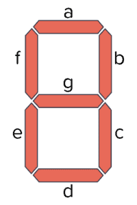
A 7-segment display is a component with seven Light-Emitting Diodes (LED) arranged as shown below. By turning on different combinations of the LEDs, a number between 0 and 9 is displayed.
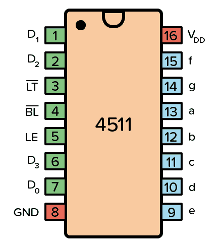
Pin Overview
| Pin Name | Pin # | Type | Description |
|---|---|---|---|
| VDD | 16 | Power | Supply Voltage (+3 to +15V) |
| GND | 8 | Power | Ground (0V) |
| a-f | 9-15 | Output | Outputs for the 7-segment display |
| D0-D3 | 7, 1, 2, 6 | Input | 4-bit data input |
| LT | 3 | Input | Lamp Test. Turns on all segments when LOW. |
| BL | 4 | Input | Blanking Test. Turns off all segments when LOW. |
| LE | 5 | Input | Latch Enable. Stores the current state when HIGH. |
What is a BCD to 7-Segment Driver?
A 7-segment display driver turns on the correct segments of a 7-segment display according to an input.
In this case, the input is Binary-Coded Decimal (BCD). For example, an input of 1001, which is 9 in decimal, would turn on the segments a, b, c, f, and g so that a “9” is displayed on the 7-segment display:

So, how exactly does this IC convert binary codes to decimal numbers? It does so by using a combination of logic gates and D flip-flops.
From the HEX4511B datasheet, we can find the internal circuit of the 4511:
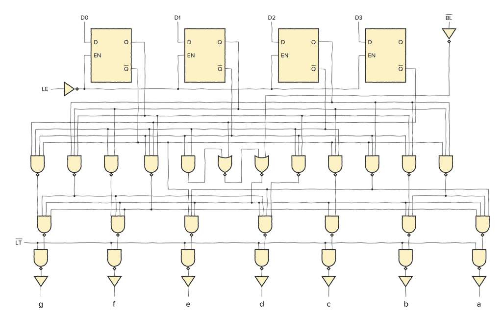
For each input bit (D0-D3), there is a D latch.
When the EN input of a D latch is HIGH, whatever is on the D input is transferred to the Q output. But when EN goes low, the last input value is stored onto the output Q and cannot change.

Build Something Useful This Evening
This gadget lets you use any IR remote-control to control your lamp, garden lights, heater oven, garage door, or anything else.
This means that when LE is LOW, the segment outputs (a to g) are determined by the data on D0 to D3. But when LE goes HIGH, the last data present on D0 to D3 is stored in the latches and the segment outputs stay unchanged.
The logic gates below convert the bits from the latches into 7-segment output.
How To Use the CD4511
To be able to use the BCD to 7-segment decoder in the chip, you need to first connect the VDD pin to the positive supply terminal and the GND pin to the negative supply terminal.
You can use a power supply voltage between 3V and 15V. Although, some versions of the 4511 chip support up to 20V. Check the datasheet of your version of the chip for exact values.
Pins D0, D1, D2, D3 are the BCD inputs through which you feed the number you want to show on the display in binary format.
Pins a to g are the output pins that you connect to your 7-segment display.
The LT (Lamp Test) pin is there to test that all the segments of the display work. Set LOW to test the segments. Set HIGH for normal operation.
The BL (Blanking Test) pin turns off all segments when LOW. You can use it to control the brightness of the display with pulse-width modulation (PWM). Set to HIGH for normal operation.
The LE (Latch Enable) pin, also called store, is used to store the current value. When HIGH, the last data is displayed regardless of the changes to the BCD inputs. Set this pin LOW for normal operation.
CD4511 Example Circuit
Below is an example circuit where you set the input number using switches. The CD4511 controls the 7-segment display so that it turns on the correct segments for displaying the number.
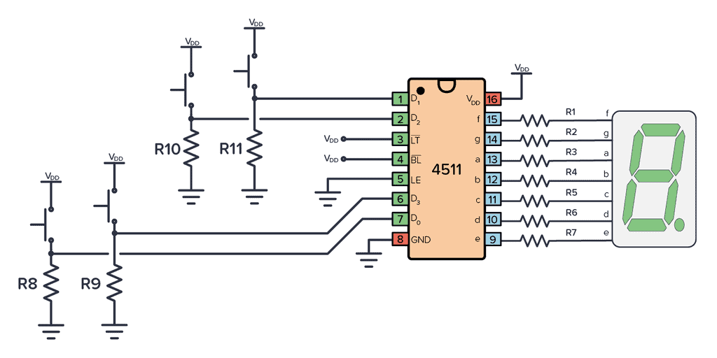
To build this circuit you’ll need:
- A 4511 chip, such as the CD4511BE
- A 7-segment display (Must be common cathode. For example LSHD-5503)
- Seven resistors (R1-R7) of 1kΩ
- Four resistors (R8-R11) of 10kΩ
- Four pushbuttons
This is a fun circuit to build as your first 7-segment display circuit. Later, you can modify the input of this circuit to instead be the output of a counter that counts seconds, to create a stopwatch.
Alternatives and Equivalents for CD4511
You likely find the 4511 IC marked as CD4511, NTE4511, MC14511, HCF4511, TC4511, or HEF4511. Usually with a few extra characters at the end (Ex: CD4511BE).
This has to do with the manufacturer of the chip and the technology used. But the functionality and the pins are the same.
Can’t find any of these in your local electronics store? Then check out my list of online stores where you can find components and tools for all your electronics projects.
Or try one of the following 7-segment decoder alternatives:
- 4026: Decade counter with 7-segment display outputs
- 4054/4055/4056: BCD to 7-segment decoder (for LCD)
- 74HC46/47/48/49: BCD to 7-segment decoder
4511 Datasheet
Download the PDF datasheet for the IC 4511 here:
CD4511B (Texas Instruments)
HEF4511B (Nexperia)
Build Something Useful This Evening
This gadget lets you use any IR remote-control to control your lamp, garden lights, heater oven, garage door, or anything else.

Excellent information.
Thank you!
Glad you liked it!
Very Helpful. I had not designed anything with ICs for over 40 years. Blame it on the Asiatic Indianization of the tech work force so I had to fall back on the electrical contracting.
Mike Cole
sur l’ Exemple de circuit CD4511
il manque la masse sur l’afficheur piloté par le CD4511, autrement, les segments ne risque pas de s’allumer
Merci de faire suive
Hi,
I like your presentation.
Can you send me a circuit example for a 6 digit, 7 seven segment display?
Thanks!
Ok so I assemble a circuit similar to this one for which it was supposed to display only the digits 1 -4 to indicate which gear an automatic transmission is in. The trans is controlled by a TCU which I assembled from a kit. I finished the display circuit and was attempting to test it. I only activated the inputs at pins 1,2,6 and 7 one at a time and made the mistake of applying the full 12v which is supplying the circuit which I used a 5v reg to power the IC. I used resistors to limit current to the LED which is a 1 inch 7 segment. I got a bright partial display that made on sensible numerical figure. Anyhow, once I realized I had made that mistake, I used the 5v side of the regulator to retest the display and very shortly I had no display at all. The display is still functional so I didn’t burn out any LED segments but now I get NO lit LEDs at all. Pretty sure I toasted the IC. I have more 4511’s but I’m nervous about installing any of them. I suppose I shouldn’t be so because as I said the 7 seg still functions and I still have a functioning Vreg section of the circuit. Point is, apparently to get a sensible output that resembles a complete numerical image more than one switch must be activated? From what I can tell, the outputs from the trans controller drive the input terminals by pull up voltages? I’m going to redo the circuit on a solderless bread board. The first circuit I assembled from a schematic supplied by the instructions to assemble the GPIO kit which is now the trans controller by way of the correct assembly kit parts package and now needs to be loaded with the firmware file so it can be programmed to control the shifting of the trans. This is a pretty simple circuit but apparently applying more voltage to the inputs than what the IC is powered by is a sure way to make it fail. Anyone do this so far?
The CD4511B can handle up to 18V, so if you used that one it shouldn’t have been a problem using 12V.
Pins D0, D1, D2, D3 are the BCD inputs through which you feed the number you want to show on the display in binary format. So for example to show the number 9, you have to input the binary 1001
The D0 to D3 counts up to 15, so how to configure it to display 0 to 9 on the 7 segment display. Thanks in advance.
It only works up to 9. If you try to count input an number above that, the output will be blank.
@BRET you need to limit the current in the BCD input pins. You probably inputted more 10mA or inputted voltage more than supply voltage VDD=12v. Make sure your input to BCD is less than your 4511 supply voltage and not more than 10mA in any input. 7-segment current limit to 15mA (20mA max.)
you can’t input current… you can only input voltage, then ohm’s law takes over. also, these have high input impedance.
Nice, a current of 20mA when supplying a voltage of 12v actually needs a resistor of 600 Ohms. This means that to apply a current lower than 10mA requires you to use much more resistance. I would recommend using resistance of 1000 Ohms and above.
This was very helpful. Thank you.
How does one connect multiple 4511 ics together to display double digit numbers?
Thanks
It depends a bit. Where is your number coming from and what format is it in?
:-)
Hi there.
Thanks for the project, a great introduction to 4511 and LED displays.
Just a question: would it be ok to put 1k resistor in series with each of the switches connected to pins 1, 2,5 and 6 (D0-D4), instead of the 10,k used in parallel with the IC inputs?
Hi, those are pull-down resistors which are needed for the switches to work properly the way they are connected. You can use 1k if you want, you just get more current flowing through them as you push them.
Thank you so much this info help me to finish my homework