The 74×137 (ex 74HC137) is a chip that contains a 3-to-8 line decoder with address latches, intended for memory address decoding and other applications where a decoder with latching inputs is required.
In this guide, you’ll learn the things you need to know about this chip in order to effectively use address decoding in your own projects.
What does the 74HC137 / 74LS137 do?
The 74×137 is a 3-to-8 line decoder/demultiplexer with address and enable inputs. It can take in three binary address inputs and will activate one of the eight outputs based on the combination of these inputs.
In addition to address inputs, it has enable inputs that must be activated for the decoder to work. If the enable inputs are not active, all outputs will be inactive regardless of the address inputs.
This chip is often used to select one out of several devices or gates, making it useful for tasks like memory addressing or signal routing.
How To Use This Chip
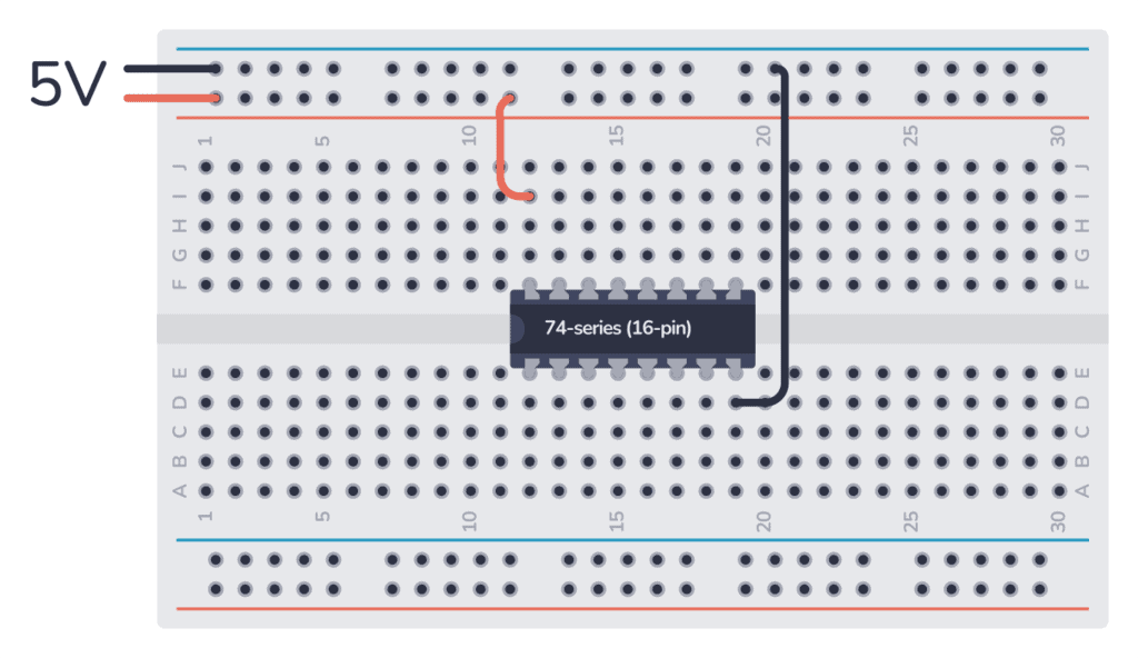
The 74HC137 comes in a 16-pin package, and you need to connect it to power before you can use it. Most 7400 ICs support a VCC voltage of 5V. One difference between the HC and LS version of the chip is that the 74HC137 supports 2V to 6V, while the 74LS137 only supports 5V.
74HC chips can normally supply a maximum of 4 mA from an output pin. If you’re using the 74LS version, the maximum current you can pull out of one output pin is 0.4 mA when the pin is high (sourcing) or 8 mA when the pin is low (sinking).
But these values can differ between models, so check the datasheet of your model to verify.

Build Something Useful This Evening
This gadget lets you use any IR remote-control to control your lamp, garden lights, heater oven, garage door, or anything else.
Once you’ve connected it to power, you can use the Demultiplexer inside.
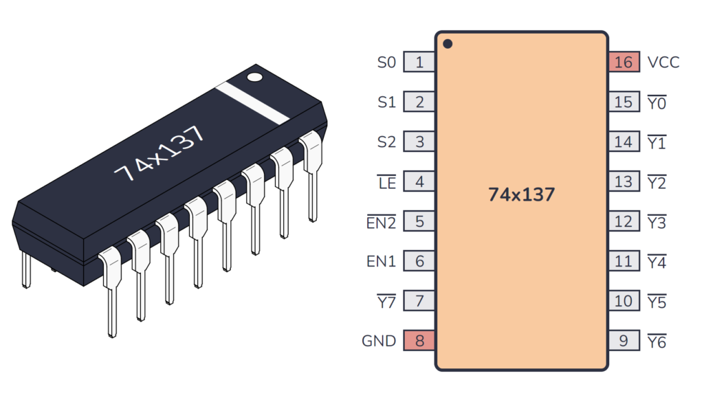
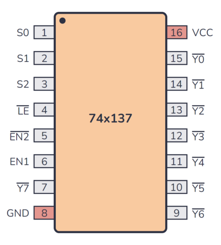
74×137 Pinout
The 74×137 has 16 pins and contains 1-of-8 inverting decoder/demultiplexer with address latches laid out as shown in the pinout diagram below:
| Pin Name | Pin # | Type | Description |
|---|---|---|---|
| S0 | 1 | Input | Select input 0 for the decoder. |
| S1 | 2 | Input | Select input 1 for the decoder. |
| S2 | 3 | Input | Select input 2 for the decoder. |
| LE | 4 | Input | Latch enable input (active low). |
| EN2 | 5 | Input | Enable input 2 (active low). |
| EN1 | 6 | Input | Enable input 1. |
| Y7 | 7 | Output | Output 7 from the decoder (active low). |
| GND | 8 | Power | Connect to ground (GND). |
| Y6 | 9 | Output | Output 6 from the decoder (active low). |
| Y5 | 10 | Output | Output 5 from the decoder (active low). |
| Y4 | 11 | Output | Output 4 from the decoder (active low). |
| Y3 | 12 | Output | Output 3 from the decoder (active low). |
| Y2 | 13 | Output | Output 2 from the decoder (active low). |
| Y1 | 14 | Output | Output 1 from the decoder (active low). |
| Y0 | 15 | Output | Output 0 from the decoder (active low). |
| VCC | 16 | Power | Positive power supply. Connect to +5V power. |
Alternatives and Equivalents for 74HC137 / 74LS137
There are many versions of the 74×137 chip. They all have the same functionality, but with different specifications such as supported voltages and maximum current output.
Here’s a list of a few equivalents of this chip:
- 74HC137 (High-speed CMOS)
- 74HCT137 (High-speed CMOS, TTL compatible)
- 74LS137 (High-speed TTL)
- 74LVC137 (Low Voltage TTL)
- 74AC137 (Advanced CMOS)
- 74ALS137 (Advanced Low-Power Schottky TTL)
- 74F137 (Very High Speed)
- 74C137 (CMOS, similar to the 4000-series)
Some manufacturers also add a prefix, such as the SN74HC137 and SN74LS137 by Texas Instruments.
Can’t find the 74×137 anywhere? Then try one of the following IC alternatives:
- 74×138 – 3-to-8 line decoder/demultiplexer.
- 74×139 – Dual 2-to-4 line decoder/demultiplexer.
- 74×238 – 3-to-8 line decoder/demultiplexer.
- 74×139 – Dual 2-to-4 line decoder/demultiplexer.
- CD4514 – 4-to-16 line decoder/demultiplexer with latches.
- CD4515 – 4-to-16 line decoder/demultiplexer with latches.
If you can’t find the 74×137 IC in your local electronics store, don’t worry, you’ll most likely find it in one of the stores listed on this page of online stores where you’ll find components and tools for all your electronics projects.
Datasheet for the 74LS137 and 74HC137 chips
Download the PDF datasheet for your version of the 74×137 here:

Get the 555 Timer Cheatsheet
A super helpful reference that makes it easy to design circuits, so that you can build oscillators, timer circuits, and more in no time.