The 74×165 (ex 74HC165) is a chip with an 8-bit parallel-in, serial-out shift register.
In this guide, you’ll learn the most important details about this chip to be able to use this type of shift register in your own projects.
What does the 74HC165 / 74LS165 do?
The 74×165 is a parallel-in, serial-out shift register. It has 8 input pins that allow you to load data in parallel, meaning you can set all 8 bits of data at once. Once the data is loaded, you can shift it out one bit at a time in a serial stream using the clock input.
Here’s how it works:
- Parallel Load: Apply a load signal, and the data on the 8 input pins is stored in the register.
- Shift Operation: After loading, each clock pulse shifts the data one position towards the serial output, allowing you to read the bits one at a time.
- Serial In: You can also shift data in, one by one, using the SER input.
This shift register is useful for reading multiple bits of data from a source like switches and sending it through single data lines, which is helpful in saving pin connections and reducing complexity in circuits like microcontrollers.
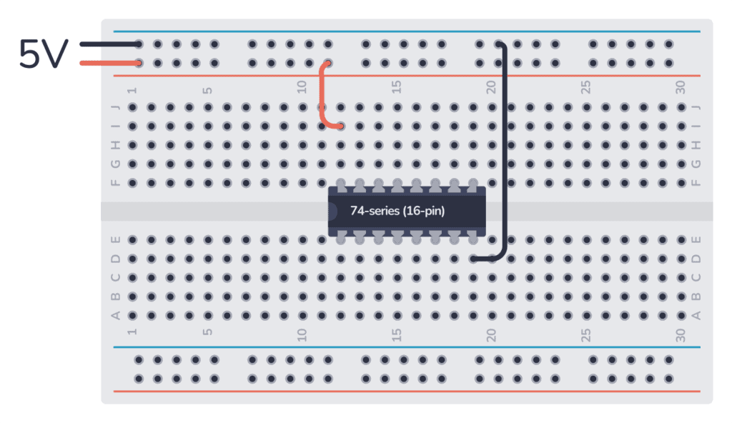
How To Use This Chip
The 74HC165 comes in a 16-pin package, and you need to connect it to power before you can use it. Most 7400 ICs support a VCC voltage of 5V. One difference between the HC and LS version of the chip is that the 74HC165 supports 2V to 6V, while the 74LS165 only supports 5V.
74HC chips can normally supply a maximum of 4 mA from an output pin. If you’re using the 74LS version, the maximum current you can pull out of one output pin is 0.8 mA when the pin is high (sourcing) or 16 mA when the pin is low (sinking).
But these values can differ between models, so check the datasheet of your model to verify.

Get the 555 Timer Cheatsheet
A super helpful reference that makes it easy to design circuits, so that you can build oscillators, timer circuits, and more in no time.
Once you’ve connected it to power, you can use the Parallel-in, serial-out shift register inside, like this:
Parallel Loading:
- Set the CLK INH pin high (1) to disable the clock.
- Attach the 8 data lines (e.g., from switches) to the input pins A to H on the 74HC165.
- Each input pin can be connected to a source that provides either a high (1) or low (0) signal, depending on whether you want to register a 1 or 0.
- Apply a low signal to the LOAD pin. This will load the data present on A to H into the shift register.
- Once loaded, switch the LOAD pin back to high to prepare for shifting.
Data Shifting:
- Set the CLK INH pin low (0) to enable the clock.
- Connect a clock signal to the CLK (clock) pin. Each pulse on the clock will shift the data one bit towards the serial output pin (QH).
- Read the serial output from the QH pin one bit at a time with each clock pulse.
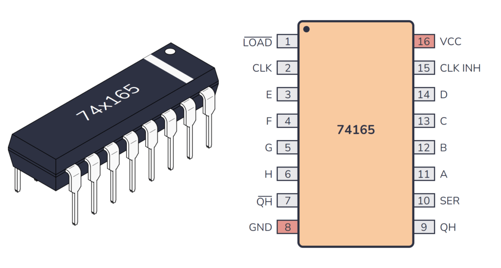
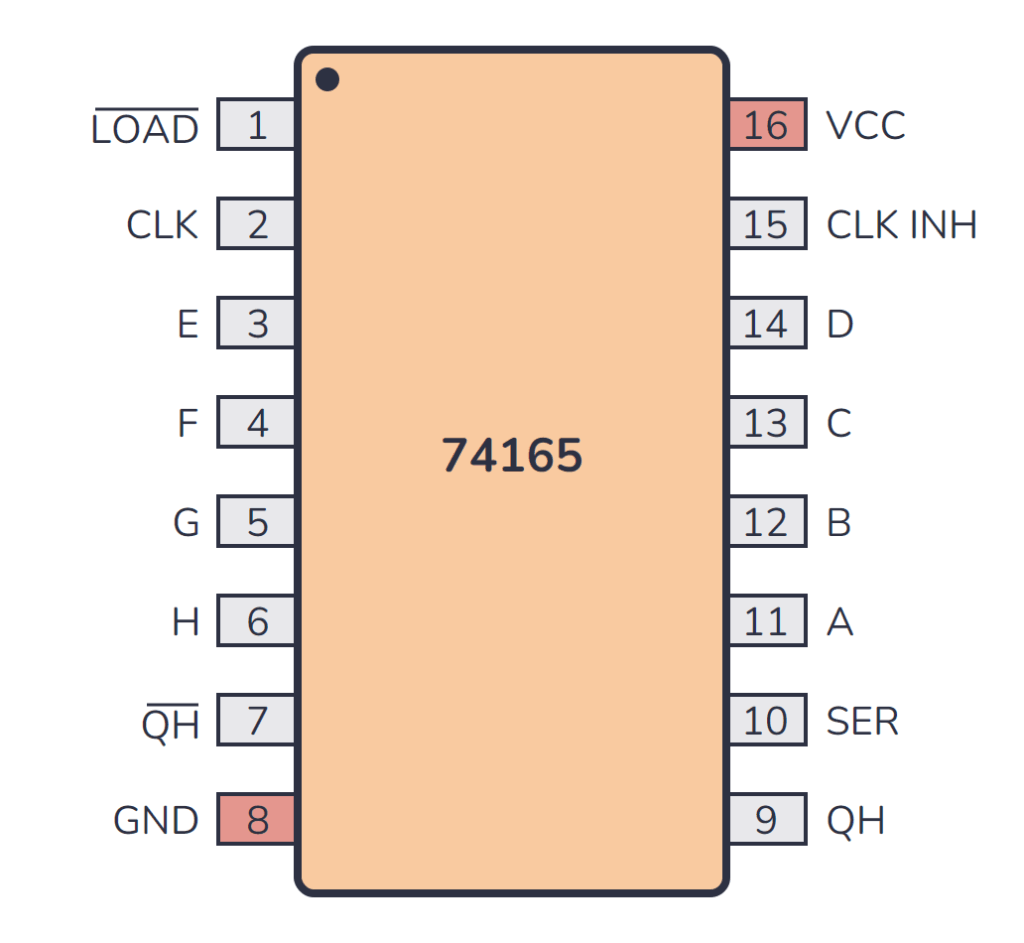
74×165 Pinout
The 74×165 has 16 pins and contains 8-bit parallel-in, serial-out shift register laid out as shown in the pinout diagram below:
| Pin Name | Pin # | Type | Description |
|---|---|---|---|
| LOAD | 1 | Input | Load control input. This pin will load in the data from pins A to H. Active low. |
| CLK | 2 | Input | Clock input for the shift register. |
| E | 3 | Input | Parallel data input bit E. |
| F | 4 | Input | Parallel data input bit F. |
| G | 5 | Input | Parallel data input bit G. |
| H | 6 | Input | Parallel data input bit H. |
| QH | 7 | Output | Complementary serial output from the last stage (inverted). |
| GND | 8 | Power | Connect to ground (GND). |
| QH | 9 | Output | QH is the true serial output from the last stage of the shift register. |
| SER | 10 | Input | Serial data input for cascading purposes. |
| A | 11 | Input | Parallel data input bit A. |
| B | 12 | Input | Parallel data input bit B. |
| C | 13 | Input | Parallel data input bit C. |
| D | 14 | Input | Parallel data input bit D. |
| CLK INH | 15 | Input | Clock inhibit input. When high, it prevents the register from clocking. |
| VCC | 16 | Power | Positive power supply. Connect to +5V power. |
Alternatives and Equivalents for 74HC165 / 74LS165
There are many versions of the 74×165 chip. They all have the same functionality, but with different specifications such as supported voltages and maximum current output.
Here’s a list of a few equivalents of this chip:
- 74HC165 (High-speed CMOS)
- 74HCT165 (High-speed CMOS, TTL compatible)
- 74LS165 (High-speed TTL)
- 74LVC165 (Low Voltage TTL)
- 74AC165 (Advanced CMOS)
- 74ALS165 (Advanced Low-Power Schottky TTL)
- 74F165 (Very High Speed)
- 74C165 (CMOS, similar to the 4000-series)
Some manufacturers also add a prefix, such as the SN74HC165 and SN74LS165 by Texas Instruments.
Can’t find the 74×165 anywhere? Then try one of the following IC alternatives:
- 74×91 – 8-bit shift register.
- 74×95 – 4-bit shift register, parallel in, parallel out, serial input.
- 74×166 – Parallel-load 8-bit shift register.
- 74×595 – 8-bit shift register with output latches.
- CD4014 – 8-bit parallel-in, serial-out shift register.
- CD4015 – Two 4-bit serial-in, parallel-out shift registers.
- CD4021 – 8-stage parallel in serial out shift register.
If you can’t find the 74×165 IC in your local electronics store, don’t worry, you’ll most likely find it in one of the stores listed on this page of online stores where you’ll find components and tools for all your electronics projects.
Datasheet for the 74LS165 and 74HC165 chips
Download the PDF datasheet for your version of the 74×165 here:
Get the 555 Timer Cheatsheet
A super helpful reference that makes it easy to design circuits, so that you can build oscillators, timer circuits, and more in no time.