fbpx

Full Adder Circuit – How it Works

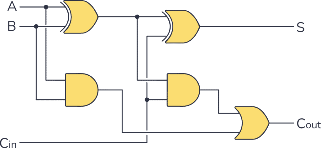
A Full Adder is a digital circuit that performs the addition of three binary inputs. In this tutorial, you will learn how this circuit works, its truth table, and how to implement one using logic gates.

Schematic for a Full Adder Circuit
A Full Adder Circuit

What is a Full Adder?

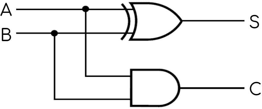
Adders can either be Half Adders or Full Adders. The difference is that the Half Adder is used to add only two 1-bit binary numbers, therefore its sum can only range from 0 to 2. To improve this performance, the Full Adder was developed. It is able to add three 1-bit binary numbers, achieving a sum range from 0 to 3, which can be expressed with two output bits (“11”). 

The S-R Latch (Quickstart Tutorial)

The S-R latch is a key circuit in digital storage units. In this tutorial, you will learn how it works, its truth table, and how to build one with different logic gates.

S-R Latch Symbol
S-R Latch Symbol

What is an S-R Latch?

Before starting with the S-R latch you need to know what a latch is. A latch is an asynchronous circuit (it doesn’t require a clock signal to work), and it has two stable states, HIGH (“1”) and LOW (“0”), that can be used for storing binary data. Many sequential circuits and larger storage devices, such as shift registers, use latches as their principal building block.

Half Adder Circuit – How it Works

Half adder circuit

A Half Adder is a digital circuit that adds binary numbers. In this tutorial, you will learn how it works, its truth table, and how to implement one using logic gates. 

Half Adder Circuit
A Half Adder Circuit

What is a Half Adder?

A Half Adder is a digital circuit that carries out the addition of binary numbers. It’s the simplest of digital adders and you can build one using only two logic gates; an XOR gate and an AND gate.