RGB LEDs are a type of LED that can emit a wide array of colors. In this tutorial, you’ll learn how RGB LEDs work and how to use them with Arduino or in other circuits to produce different colors.

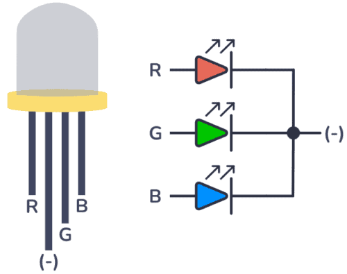
A Light-Emitting Diode (LED) is a small component that illuminates when current flows through it. RGB LEDs operate on the same principle, but they internally contain three LEDs (Red, Green, and Blue) capable of combining to produce nearly any color output.