In this episode, we start out with the idea of building a buck converter with a microcontroller. We realize that we’ve never built a buck converter before, so we go through our thought process live to figure out what we need to do.
We built one buck converter each. Elias used a Bluepill and Oyvind used an Arduino. Then we talk about the process and what we learned during the build.
Listen to the Podcast
Show Notes
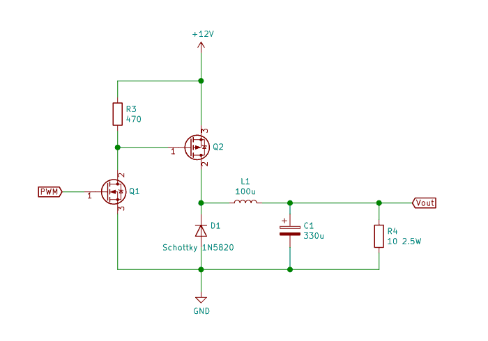
The buck converter circuit diagram Oyvind ended up with:
The Arduino Code Oyvind used:
#define PIN_INPUT A5
#define PIN_OUTPUT 9

int pwm_val = 10;

void setup() {
  Serial.begin(115200);

  // PWM frequency:
  TCCR1B = TCCR1B & B11111000 | B00000001; // 31372.55 Hz
  //TCCR1B = TCCR1B & B11111000 | B00000010; // 3921.16 Hz
  //TCCR1B = TCCR1B & B11111000 | B00000011; // 490.20 Hz (The DEFAULT)
  //TCCR1B = TCCR1B & B11111000 | B00000100; // 122.55 Hz
  //TCCR1B = TCCR1B & B11111000 | B00000101; // 30.64 Hz
}

void loop() {
 double volt = getVoltage();

 if (volt > 5.1)
    pwm_val--;
 else if (volt < 4.9)
    pwm_val++;

 if (pwm_val > 255)
  pwm_val = 255;
 if (pwm_val < 0)
  pwm_val = 0;

 analogWrite(PIN_OUTPUT, pwm_val);
 Serial.print(volt);
 Serial.print(" - Setting output to ");
 Serial.println(pwm_val);

}

double getVoltage() {
  int in = analogRead(PIN_INPUT);
  double input_volt = 5.0 * in/1024;
  //Serial.print("Input: ");
  //Serial.println(input_volt);

  return input_volt/0.18;
}
More Podcast Tutorials

Get Our Basic Electronic Components Guide
Learn how the basic electronic components work so that circuit diagrams will start making sense to you.
