In 2017, I started using KiCad as an alternative to Eagle.
For those unfamiliar with these programs: they are programs you use to design a printed circuit board (PCB).
And I decided to create a quickstart introduction to KiCad.
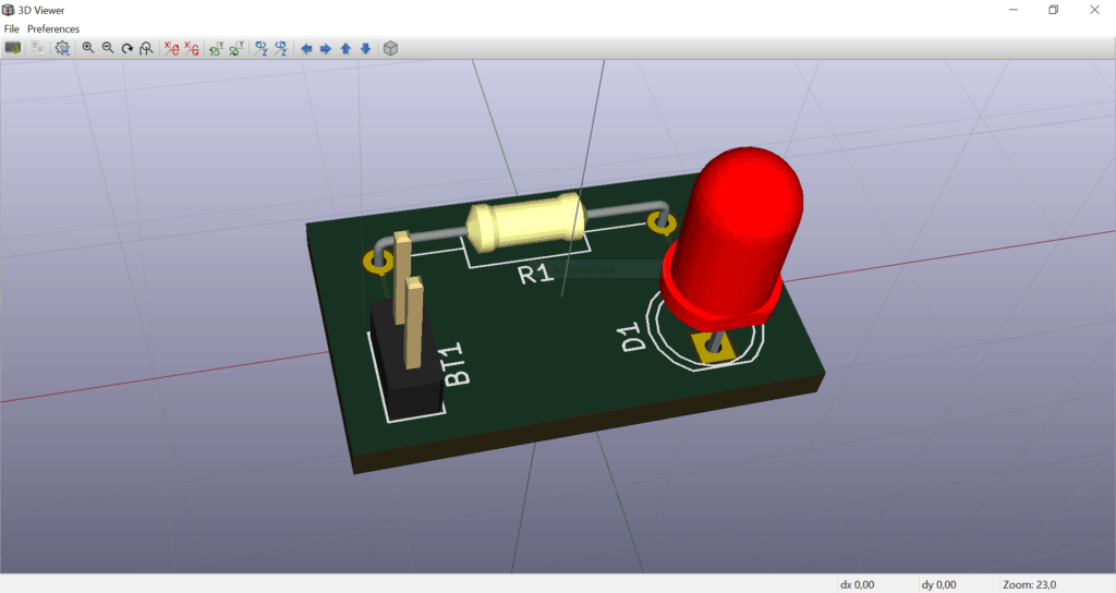
In this 5-minute video you’ll see how to design a simple circuit board from scratch:
The purpose of the video is to show you all the steps necessary to create a board in KiCAD.
You won’t become an expert from this video.
If you want to take it one step further, check out my KiCad Tutorial for beginners. I’ve also created several courses on how to use KiCad that I’ve published on Ohmify.
It’s more for getting you that feeling of “huh, that’s not too bad… I can do that!”
Make Your First Printed Circuit Board
Download my guide with all the steps you need to design your first printed circuit board (PCB) from scratch.
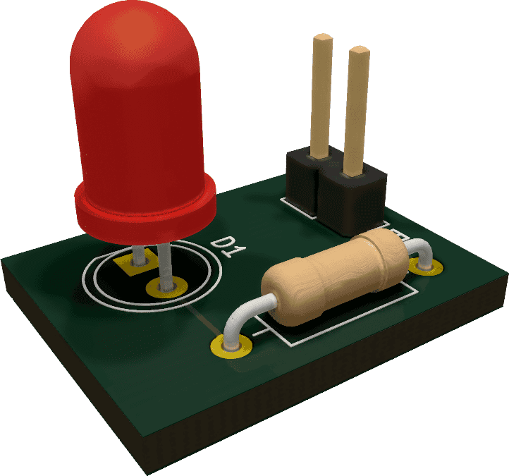
Here’s the board you’ll design:
Let me know your biggest struggle when it comes to designing a PCB in the comment field. I’ll read all the comments and these will help shape the future KiCad courses and tutorials.
More KiCad Tutorials
Make Your First Printed Circuit Board
Download my guide with all the steps you need to design your first printed circuit board (PCB) from scratch.
This is interesting.
your book and comments are interesting and is really a person who is interrsted in ELECTRONICS will never leave until he lays his hands on the book as well as the components that are going to make up several interesting cir uits.
sreenivasan
Glad to hear that!
I would like to make a pcb of a set size as a “backpack” to fit on the rear of a 2.8 inch tft display, but I can’t find how to set the size and mounting centres. Seems that all pcb software relies on a schematic first and creates the pcb size to suit
Any advice please
Regards
Jim
Hey Jim,
Yes, normally you would always want to add at least one component to the PCB and therefore it makes sense to start with the schematics.
But if you don’t want any components, only holes – in KiCad you could add a Conn_01x01 for each hole and use the footprint called 1pin. In the pcb editor you can “Edit Pad” to change the size of the hole.
It might be that Fritzing is an easier tool for this purpose.