The CD4073 is a CMOS chip with three 3-input AND gates. Because each gate has three inputs and it has three gates inside, it’s usually called a Triple 3-Input AND Gate.
An AND gate is a basic logic gate that checks if all its inputs are HIGH. So the output from a 3-input AND gate will only be HIGH if all three inputs are HIGH.
Pin Overview
| Pin Name | Pin # | Type | Description |
|---|---|---|---|
| VDD | 14 | Power | Supply Voltage (+3 to +15V) |
| GND | 7 | Power | Ground (0V) |
| A1 to A3 | 1, 3, 13 | Input | Inputs A of the three AND gates |
| B1 to B3 | 2, 4, 12 | Input | Inputs B of the three AND gates |
| C1 to C3 | 5, 8, 11 | Input | Inputs C of the three AND gates |
| Q1 to Q3 | 6, 9, 10 | Output | Outputs from the three AND gates |
What is a 3-input AND gate?
An AND gate with three inputs will only give out HIGH if all inputs are HIGH (input 1 AND input 2 AND input 3). You can see the truth table below.

| Input A | Input B | Input C | Output Q |
|---|---|---|---|
| 0 | 0 | 0 | 0 |
| 0 | 0 | 1 | 0 |
| 0 | 1 | 0 | 0 |
| 0 | 1 | 1 | 0 |
| 1 | 0 | 0 | 0 |
| 1 | 0 | 1 | 0 |
| 1 | 1 | 0 | 0 |
| 1 | 1 | 1 | 1 |
How To Use the CD4073?
First of all, you need a power supply voltage of 3 to 15V. Some versions of the chip support up to 20V. Check the datasheet of your version of the chip for exact values.
To be able to use any of the AND gates in the chip, you need to first connect the VDD pin to the positive supply terminal and the GND pin to the negative supply terminal.
The A, B, and C pins are the inputs to the three AND gates in the IC.
The Q pins are the outputs from the AND gates.
CD4073 Example Circuit – Code Lock
3-input AND gates can for example be used to check for a secret code. In the schematic below, the secret 6-bit code is 101101. The AND gates check if its inputs are “1” (HIGH), so to hardcode the secret of a bit to “0” (LOW), NOT gates (inverters) are used for those bits. If the DIP switch is set to this code (101101), the transistor turns the relay on.

Get the 555 Timer Cheatsheet
A super helpful reference that makes it easy to design circuits, so that you can build oscillators, timer circuits, and more in no time.
Connect whatever you want to activate when the code is right (alarm, electric lock, secret door, etc) through the relay.
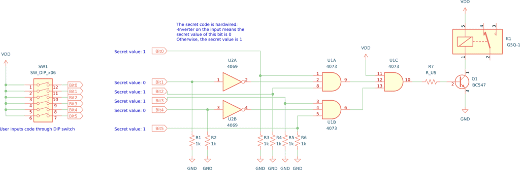
To build this you’ll need:
- A relay
- A chip with 3-input AND gates such as the CD4073BE (U1)
- A chip with NOT gates such as the CD4069BE (U2)
- DIP switch with 6 positions (SW1)
- 6 x 1 kΩ resistors (R1-R6)
- 10 kΩ resistor (R7)
- NPN transistor such as the BC547 (Q1)
Alternatives and Equivalents for CD4073
You likely find the 4073 IC marked as CD4073, NTE4073, MC14073, HCF4073, TC4073, or HEF4073. Usually with a few extra characters at the end (Ex: CD4073BE).
This has to do with the manufacturer of the chip and the technology used. But the functionality and the pins are the same.
If they don’t have any of these chips in your local electronics store, check out my list of online stores where you can find components and tools for all your electronics projects.
Can’t find the 4073? Then try one of the following IC alternatives with 2-input AND gates:
- 74HC11: Triple 3-input AND
4073 Datasheet
Download the PDF datasheet for the IC 4073 here:
CD4073B (Texas Instruments)
HEF4073B (Nexperia)
Go back to the full overview of the 4000-series integrated circuits

Build Something Useful This Evening
This gadget lets you use any IR remote-control to control your lamp, garden lights, heater oven, garage door, or anything else.