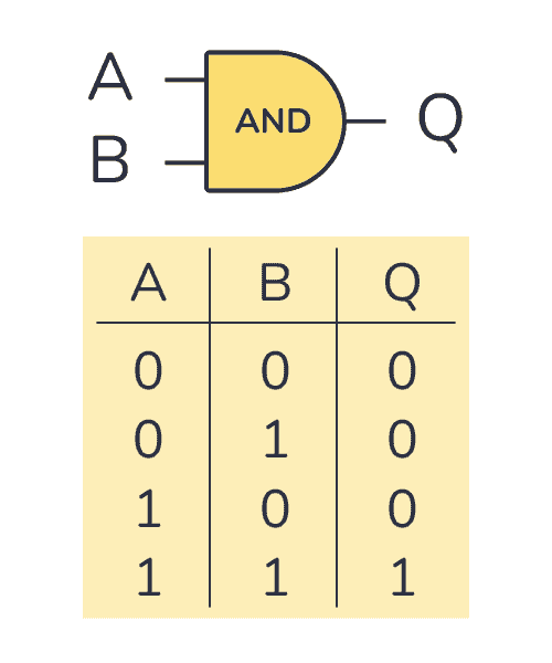
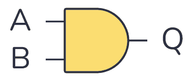
An AND gate is a logic gate where the output goes HIGH (or “1”) only if all its inputs are HIGH. So if the inputs A AND B are HIGH, the output Q will also be HIGH.
The logic or Boolean expression for an AND gate is  which means that:
If A and B are true, then Q is true
Truth Table
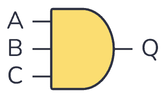
AND gates can have more than two inputs. But no matter how many inputs it has, it will only give out a HIGH or logic “1” if all its inputs are HIGH. As soon as one of the inputs goes LOW, the output goes LOW too.
2-input AND Gate Truth Table
| Input A | Input B | Output Q |
|---|---|---|
| 0 | 0 | 0 |
| 0 | 1 | 0 |
| 1 | 0 | 0 |
| 1 | 1 | 1 |
3-input AND Gate Truth Table
| Input A | Input B | Input C | Output Q |
|---|---|---|---|
| 0 | 0 | 0 | 0 |
| 0 | 0 | 1 | 0 |
| 0 | 1 | 0 | 0 |
| 0 | 1 | 1 | 0 |
| 1 | 0 | 0 | 0 |
| 1 | 0 | 1 | 0 |
| 1 | 1 | 0 | 0 |
| 1 | 1 | 1 | 1 |
IC Alternatives with AND Gates
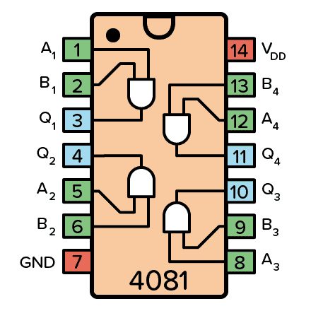
If you want to experiment and build circuits with AND gates, you’ll find them in both the 4000 IC series and the 7400 IC series:
- 4081: Four 2-input AND gates
- 4073: Three 3-input AND gates
- 74HC08: Four 2-input AND gates (HC is the family, can also be LS/HCT/…)
- 74HC09: Four 2-input AND gates (HC is the family, can also be LS/HCT/…)
- 74HC11: Three 3-input AND gates (HC is the family, can also be LS/HCT/…)
These should all be available as hobbyist-friendly through-hole chips. Just make sure you buy the DIP package version.
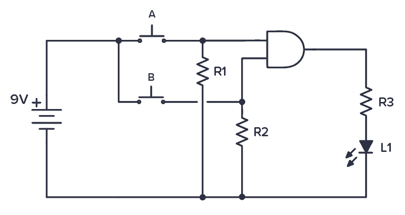
Example Circuit: Testing the AND gate
Below is a circuit that you can build to demonstrate how an AND gate works.
Normally, both inputs to the AND gate are LOW because of the pull-down resistors. When you push any of the push buttons, you’ll make the input pin HIGH.

Get Our Basic Electronic Components Guide
Learn how the basic electronic components work so that circuit diagrams will start making sense to you.
The Light-Emitting Diode (LED) on the output shows the result. A lit LED represents a HIGH output. An unlit LED represents a LOW output. As you’ll see, the LED will only turn on if you push both buttons at the same time.
More Logic Gates Tutorials

10 Simple Steps to Learn Electronics
Electronics is easy when you know what to focus on and what to ignore. Learn what "the basics" really is and how to learn it fast.
Can you show the value of the resister?
R1, R2 can be 50k.Voltage bias Low.
R3 can be 1k current limit