The JK Flip-Flop is a type of flip-flop that can be set, reset, and toggled. It can be used for making counters, event detectors, frequency dividers, and much more.
In this tutorial, you will learn how it works, its truth table, and how to build one with logic gates.

What is a JK Flip-Flop?
Flip-flops are components that can store a digital value on their output. They have a Clock input (Clk) which determines when they can change the state of their output.
Contrary to what you’d think, the two inputs of the JK Flip-Flop, “J” and “K”, are not abbreviations for what the pins do (which is the case for the S-R latch). They were chosen by its inventor Jack Kilby (JK) to distinguish his flip-flop design from other types.
You can see a basic implementation of the circuit below. It’s based on the S-R latch and built with NAND gates:

The J and K inputs of the JK flip-flop can be used to set, reset, or toggle the output, like this:
- J=1 and K=0 sets the output to 1
- J=0 and K=1 reset the output to 0
- J=1 and K=1 toggle the output
But for the flip-flop to make any change, its Clock input must be 1. Check out the truth table below:
| Clk | J | K | Q | Description |
|---|---|---|---|---|
| 0 | X | X | Q | Clk in 0 no change in Q |
| 1 | 0 | 0 | Q | Memory (no change) |
| 1 | 1 | 0 | 1 | Set |
| 1 | 0 | 1 | 0 | Reset |
| 1 | 1 | 1 | Q̅ | Toggle |
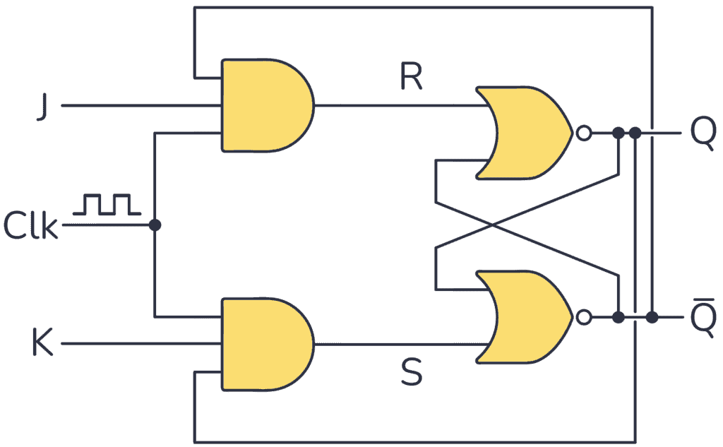
An alternative way to implement the basic JK flip-flop circuit is using two AND gates and two NOR gates as follows (it works exactly like the one built with NAND gates):

Get Our Basic Electronic Components Guide
Learn how the basic electronic components work so that circuit diagrams will start making sense to you.
Racing Problem
In principle, the basic implementation above works, but a timing problem arises. When the clock is “1” and you want to toggle the output, it will toggle really fast between “1” and “0” until the clock goes back to “0”. This issue is called a race condition.
You can solve this by making the flip-flop pulse-triggered or edge-triggered.
Pulse-Triggered JK Flip-Flop
Below you have a pulse-triggered JK flip-flop based on the Master-Slave principle:

As you can see, to build this configuration you need a basic JK Flip-Flop circuit tied together with an S-R flip-flop.
To understand how this version works check out its timing diagram below:

As soon as the clock makes a rising edge ↑, which is a change from 0 to 1 (0→1), it triggers the master section. As a result, the value of the outputs in this section changes. These signals are connected to the slave section, but this doesn’t trigger on the rising edge because the clock has been inverted.
Once the clock signal produces a falling edge ↓, a change from 1 to 0 (1→0), it triggers the slave section, causing the Q output to reflect the master’s output value.
So this circuit requires a complete pulse (0→1 →0) in order to change the output. That’s why this configuration is called pulse-triggered JK Flip-Flop.
| Clk | J | K | Q | Description |
|---|---|---|---|---|
| 0 or 1 | X | X | Q | No pulse no change |
| 0→1 →0 | 0 | 0 | Q | Memory (no change) |
| 0→1 →0 | 1 | 0 | 1 | Set |
| 0→1 →0 | 0 | 1 | 0 | Reset |
| 0→1 →0 | 1 | 1 | Q̅ | Toggle |
Edge-Triggered JK Flip-Flop
Unlike the Master-Slave design, which needs a complete pulse, you can also build an edge-triggered design that triggers from a rising edge ↑ or a falling edge ↓.
Below you have the timing diagram for one that triggers on the rising edge:

The above picture shows how this circuit just needs a rising edge on the Clk input to change the state of the output Q. And it will only change on the rising edge.
| Clk | J | K | Q | Description |
|---|---|---|---|---|
| 0 or 1 | X | X | Q | No rising edge no change |
| 0→1 (↑) | 0 | 0 | Q | Memory (no change) |
| 0→1 (↑) | 1 | 0 | 1 | Set |
| 0→1 (↑) | 0 | 1 | 0 | Reset |
| 0→1 (↑) | 1 | 1 | Q̅ | Toggle |
To build a JK Flip-Flop that triggers only with rising edge signals, you can use a rising edge-triggered D flip-flop, a NOT gate, and NAND gates as follows:

Integrated Circuits With JK Flip-Flop
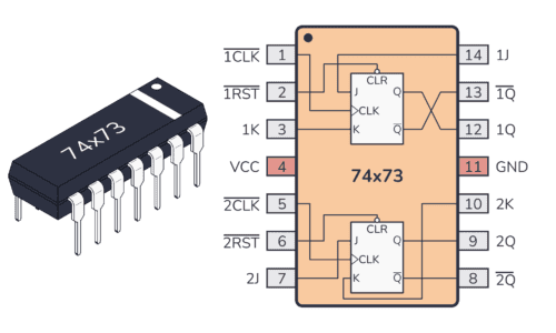
Need a JK Flip-Flop? You don’t have to build it from scratch. There are many integrated circuits with JK Flip-Flop circuits inside. Two common choices are the CD4027 chip or the 74HC73 IC.
Questions?
Do you have any questions about how this type of flip-flop works? Let me know in the comments below.
More Digital Electronics Tutorials

10 Simple Steps to Learn Electronics
Electronics is easy when you know what to focus on and what to ignore. Learn what "the basics" really is and how to learn it fast.