In this short and simple tutorial I am going to walk you through how to use the Eagle autorouter with net classes.
The net classes feature lets you select different widths for each net. This is useful if you for example want your power traces to be thicker than your signal traces.
In this example we’ll set up a new net class for our ground net. And we’ll set the default width for all the other nets.
Scroll down to the bottom if you prefer a video tutorial instead.
Step 1: Setup net classes
We’ll start with setting up the net class for our ground net. To set up a net class, go to schematic view and click “Edit -> Net Classes”.
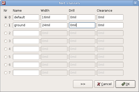
Here you can set up the width, drill size and clearance of a net. The “default” net is the one that is used by default. We’ll start by setting the width to 16 mil.

10 Simple Steps to Learn Electronics
Electronics is easy when you know what to focus on and what to ignore. Learn what "the basics" really is and how to learn it fast.
Add a new class by clicking on the next unused line. Type in a descriptive name such as “ground”. Set the with of this net class to 24mil.
Step 2: Set the correct net class for each net
As mentioned, all nets will have the net class “default” by default. If you want to change to another net class, choose “Info” from the “View” menu.
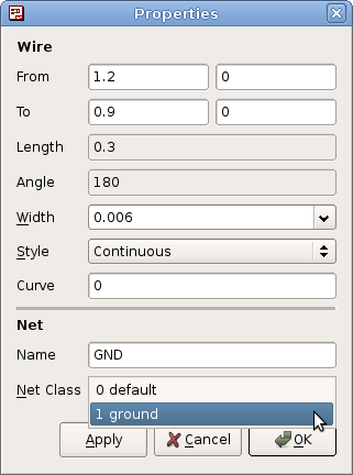
Select the net you want to change and at the bottom choose the net class you want for this net. Then click “Ok”.
The net classes must be set before you route your board. Changing the settings afterwards will not affect the already routed nets.
Step 3: Run the Eagle autorouter
It is time to use the autoroute function. Switch to board view and place your components on the board (if you haven’t already).
Then choose “Auto…” from the “Tools” menu. A window with lots of different settings pops up.
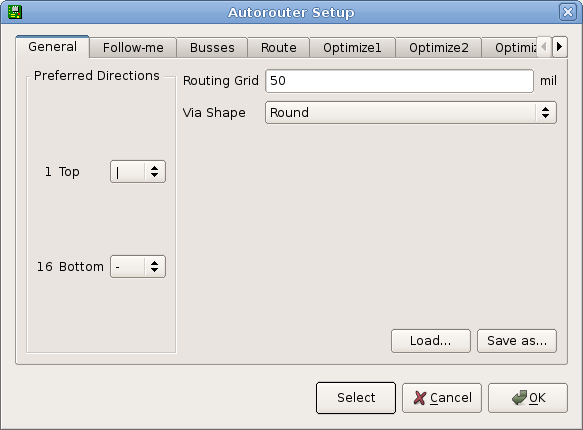
In this window you can set different rules for the autorouter to optimize its behaviour for your needs. If you don’t know what to do here, just ignore it and use the default options.
Click “Ok”
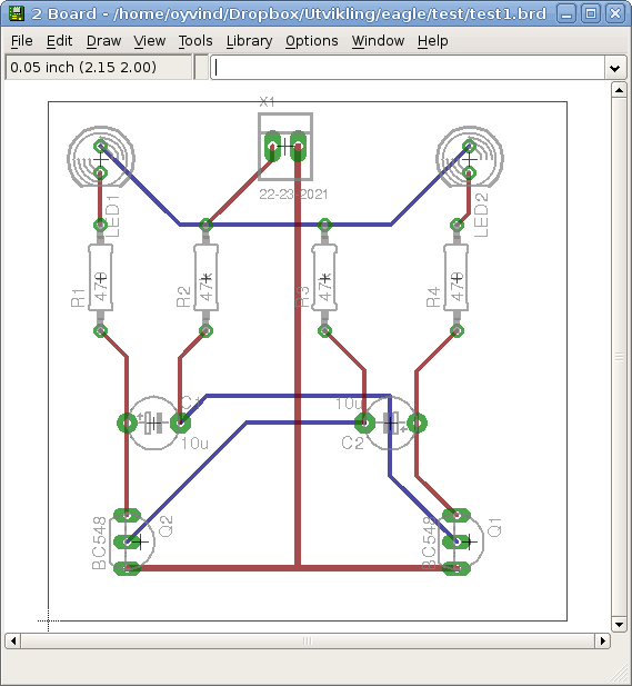
Voila! Your board is routed automatically.
Note:
The autorouter is not very smart. With complex boards you cannot expect to just run the autorouter and get everything routed perfectly. But you can also combine the autoroute with manual routing.
Video tutorial:
Post your questions and comments in the comment field below.
Related articles
- Beginner’s guide to Eagle CAD
- PCB Layout Tutorial
- Learn how to draw a ground plane in Eagle.
- How To Create a Gerber File Using Eagle
Return from Eagle Autorouter to PCB Design
10 Simple Steps to Learn Electronics
Electronics is easy when you know what to focus on and what to ignore. Learn what "the basics" really is and how to learn it fast.

What do Preferred directions mean for Top and Bottom layers (-, !, /,\, etc.)? I am looking how to manually force certain routes to be on one or another layer.
In Eagle when I created part and place it inti Schematic and after Board Autorouter old components are Routed but created part are NOT Routed , if I try to Single Route this are these Routed.
autorouter does not route anything with your method