What Is an H-Bridge?

H-bridge prototype on breadboard

An H-bridge is a simple circuit that lets you control a DC motor to go backward or forward.

You normally use it with a microcontroller, such as an Arduino, to control motors.

When you can control two motors to go either forward or backward – you can build yourself a robot!
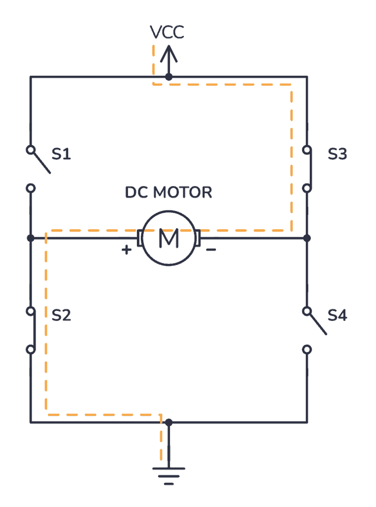
H-Bridge concept

Here’s the concept of the H-bridge:

An H-bridge with switches

A DC motor spins either backward or forward, depending on how you connect the plus and the minus.

If you close switch 1 and 4, you have plus connected to the left side of the motor and minus to the other side. And the motor will start spinning in one direction.
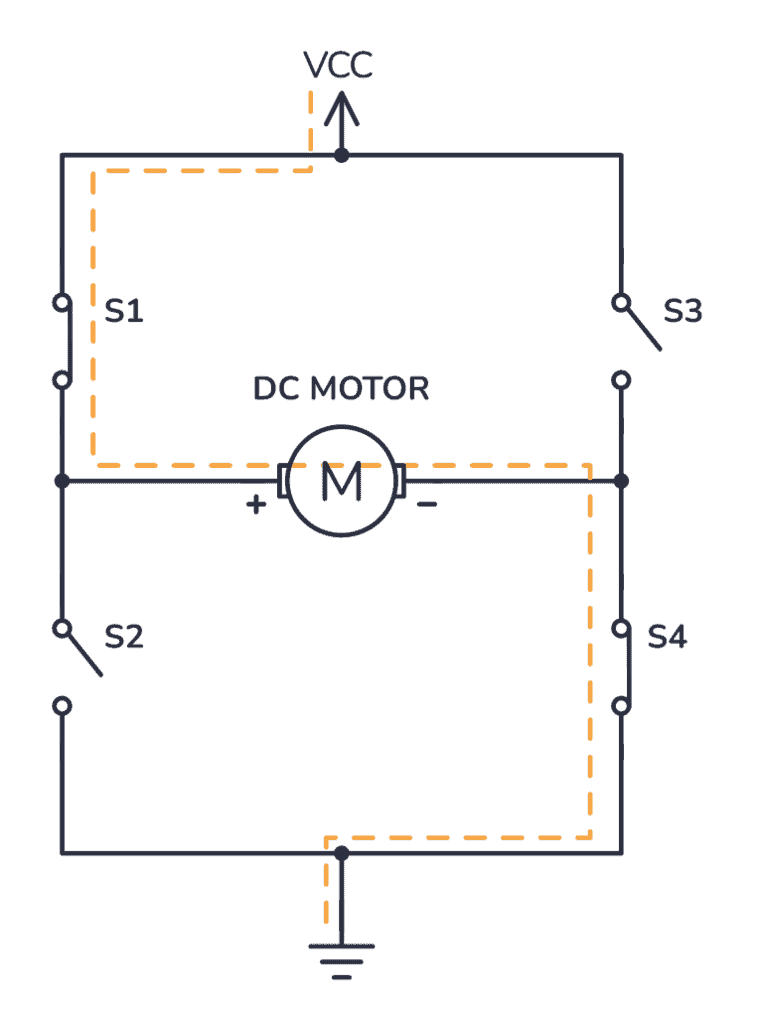
If you instead close switch 2 and 3, you have plus connected to the right side and minus to the left side. And the motor spins in the opposite direction.

The H-Bridge circuit

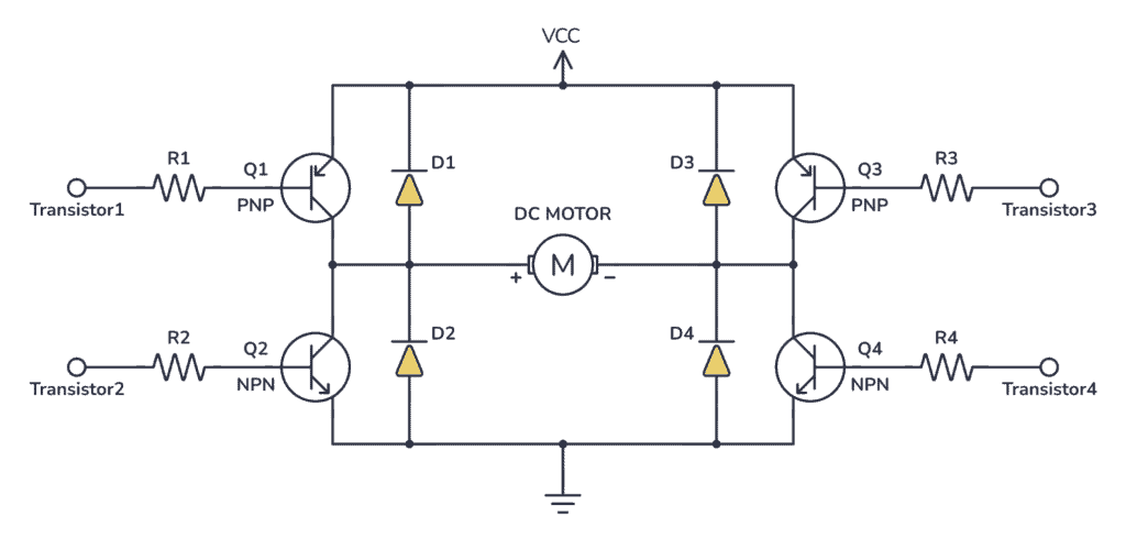
You can build an H-bridge with four transistors.

If you’re not sure how the transistor works, I recommend you read the article How Transistors Work first. From there you’ll learn that the transistor can work as a switch that you can open and close with the voltage on the base.

A simple H-bridge with BJT transistors

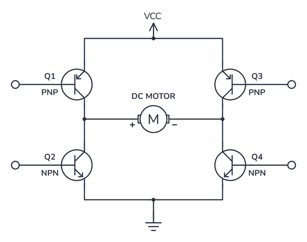
Since the transistor can be a switch, you’ll be able to make the motor spin in either direction by turning on and off the four transistors in the circuit above.

Usually, you control the transistors from a microcontroller, such as Arduino.

What Transistors To Use?

The transistors you choose must:

  • Handle enough current
  • Use PNP (or pmos) at the top
  • Have a low voltage drop between collector and emitter

Current

The most important thing is that all the transistors can handle enough current for the motor. Otherwise it will burn out.

For example, if the motor draws 1 Ampere of current, you need transistors that can handle a minimum of 1 Ampere.

PNP (or pMOS) transistors at the top

Next, you see I have chosen PNP transistors on the top, and NPN transistors on the bottom.

What turns the transistor on or off is the voltage difference between the base and the emitter.

With PNP transistors at the top, you can use a higher voltage for VCC than you use for the base of the transistors.

For example, you can use 3.3V outputs from a microcontroller and 9V for Vcc.

That won’t work if you have NPNs at the top since the emitter will be 0.7V lower than the base. Because that turns into 3.3V – 0.7V = 2.6V at the positive side of the motor, no matter what VCC voltage you choose.

Low voltage drop between collector and emitter

While building a robot in Colombia, I tried to make this circuit using TIP120 and TIP127 transistors.

That did not work.

TIP12x transistors give a 2V drop from the emitter to collector.

In such a configuration, you’d end up with a loss of 4V over the transistors. I was trying to connect this to an Arduino, using its 5V supply, but failed because it was only 1V left for the motor!

Here’s a nice article/rant about the topic: Stop using antique parts!

Basically, it says that the TIP transistors are antiques that you shouldn’t use anymore exactly because of this huge voltage drop.

Choose transistors with low voltage drop. For example BD135/BD136 or MOSFET transistors.

Protection diodes and PWM mode

A side-effect of how a motor works is that the motor will also generate electrical energy. When you disable the transistors to stop running the motor, this energy needs to be released in some way.

If you add diodes in the reverse direction for the transistors, you give a path for the current to take to release this energy. Without them, you risk that the voltage rises and damages your transistors.

H-bridge circuit using BJT transistors with diode protection

You can read more about this – and what to keep in mind if you want to use a PWM signal to control the speed of the motor, in this article.
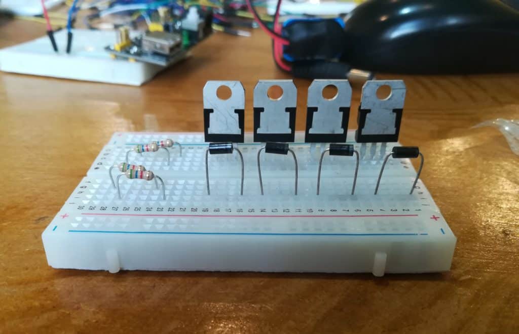
The resistors going into each base is there to reduce the current to each transistor. Not sure how to calculate it? If you’re using a microcontroller to control them, start with 1k and adjust if that doesn’t work.

Questions or comments?

Have you built an H-bridge before? Or do you have questions about the H-bridge? Let me know in the comments field below:

More Transistors Tutorials

29 thoughts on “What Is an H-Bridge?”

      • Sadly in my experience a Mosfet can only be used as a Drain, rather that a source, try it, simply place your motor and a N- Channel Mosfet on a bread board, Using the Vcc connected to the Motor, and ground, then reverse the Motor connections, placing the gnd to the M/F source pin, and Motor to Vcc……

        Reply
    • All this talk about BJT vs MOSFET & not 1 circuit discription nor circuit using MOSFETS.
      Whereas you could have just used a suitable MOSFET that would be far sufficient enough to run any Voltage requirement & has inbuilt Diodes to prevent Electromagnet Current return from the motor.

      Reply
  1. Nice clear explanation. You might want to add a caution about not turning on both left or both right transistors at the same. That would give you a short across your transistors.

    In a similar vein, controlling with an Arduino, make sure that the default outputs turn all 4 transistors off while in reset. Lastly, make sure to send commands to Turn Off the transistors before sending commands to Turn On transistors. Again, you don’t want to short out your transistors

    Reply
      • I think that transistors Q1 and Q4 will be engaged for one direction of the motor and then to reverse the direction of the motor Q1 and Q4 will be disengaged and Q2 and Q3 can then be engaged to run the motor in the reverse direction. If the motor is manually turned and there is enough residual magnetism in the motor windings to produce a current the diodes D1 thru D4 will shunt this current off to protect the transistors.

        Reply
  2. Great article, explained in very simple and effective manner. Just following suggestions:

    – Would be good to mention 3.3 V is being applied at base
    – How to select Diode
    – Calculation to select the resistor value

    Reply
    • It allows a dc motor to either move in forward or backward direction. As you don’t want yourself to change the wires of the motors if you want to move your car in opposite direction. ;)

      Reply
  3. Oh! This is so educative that the explanation was just storing into my number 6… Thanks so much, Oyvind. But a question sir, does this circuit automatically amplify power from Arduino output? Because I think if one connects a motor to Arduino, it will run but slowly.

    Reply
    • Glad you liked it! An H-bridge does not take power from the Arduino, but from the power supply. The Arduino only controls the on/off of the motors.

      Reply
    • If you connect a PWM signal directly to a DC motor, you could control the speed, but not the direction.

      Also, the PWM signal is usually given by a microcontroller which won’t be able to give enough current to drive the motor.

      Reply
  4. In last figure what does the operation of the four transistors. By supplying +vcc to the motor right pin it will turn clockwise and – VCC for counter clockwise at the right pin of the motor. What will happen to the four transistors when the motor turn clockwise and counter-clockwise on the other hand.

    Reply
    • To go in one direction, turn on transistor 1 and 4. To go in the other direction, turn on transistor 2 and 3.

      If you try other combinations, you’ll risk shorting your power supply, so that’s something you should avoid.

      Reply
    • If you try to make the motor go in both directions at once you basically short circuit the power supply. The transistor might go up in smoke from all the current that will pass through them.

      Reply
  5. Excellent article! When using an arduino or similar, make sure to turn off the circuit that is driving the motors before changing the direction of the motor. You would do that in your program, perhaps with the delay() function, but also turns off any other processing going on as well, there are other ways to turn the outputs off.

    Make sure to examine at least a few use cases, for example:
    1. Motor forward mode, change to Motor reverse mode. This use case is important as pointed out this could short your transistors.
    2. Overload, if the motor stalls, can you detect it? Will there be “back” EMF or voltage that could damage the circuit. If you are using a device with an IMU like the Intel Arduino 101 board or similar you could detect the lack of motion and turn off the motors with no additional hardware.

    And so forth. But this article was short and a excellent refresher.

    Reply
  6. Thanks for your teaching.
    with the h-bridge, how would you use / measure the voltage resulting from the magnetic effect ?
    “A side-effect of how a motor works is that the motor will also generate electrical energy. When you disable the transistors to stop running the motor, this energy needs to be released on some way.”

    Reply
    • Hi Ted,
      You can measure the voltage across the motor in an oscilloscope and look at the voltage in the milliseconds after you disconnect the power. But the voltage will vary depending on what you have connected there. Even the oscilloscope might affect the reading. Using a 10x probe will minimize the effect the oscilloscope has on the reading.

      Reply
  7. It’s much more common, but requires the use of a real gate driver, to use N-channel MOSFETS at the top due to their lower RDSon, which makes them more efficient and relieves the excessive heat generation for which P-channel MOSFETs are famous.

    Reply

Leave a Comment