The PNP transistor was a mystery to me for a long time. But when I at some point was forced to learn it, I realized that it was pretty simple. And if you want to design circuits with transistors, it’s really worth knowing about this type of transistor.
For example, want to automatically turn on a light when it gets dark? The PNP transistor will make this easy for you. Let’s dive in!
In my article how transistors work, I explained how a standard NPN transistor works. If you haven’t already, I’d really urge you to read that article first.
If you understand the NPN transistor, it will make it easier to understand the PNP transistor. They work pretty much in the same way, with one major difference: The currents in the PNP transistor flow in the opposite directions of the currents in the NPN transistor.
Note: This topic is much easier with an understanding of current flow and voltages.
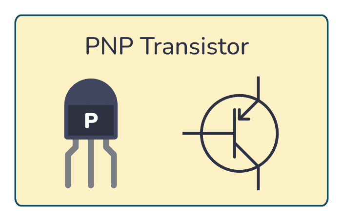
How PNP Transistors Work
The PNP transistor has the same leg names as the NPN:
- Base
- Emitter
- Collector
A PNP transistor will “turn on” when you have a small current running from emitter to base of the transistor. When I say “turn on”, I mean that the transistor will open up a channel between emitter and collector. And this channel can carry a much larger current.
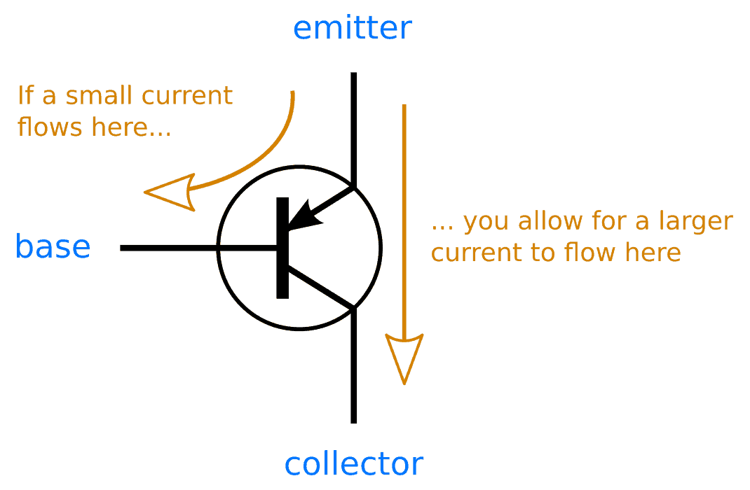
To get current running from emitter to base, you need a voltage difference of about 0.7V. Since the current goes from emitter to base, the base needs to be 0.7V lower than the emitter.

10 Simple Steps to Learn Electronics
Electronics is easy when you know what to focus on and what to ignore. Learn what "the basics" really is and how to learn it fast.
By setting the base voltage of a PNP transistor to 0.7V lower than the emitter, you “turn the transistor on” and allow for current to flow from emitter to collector.
I know this can sound a bit confusing, so read on to see how you can design a circuit with the PNP transistor.
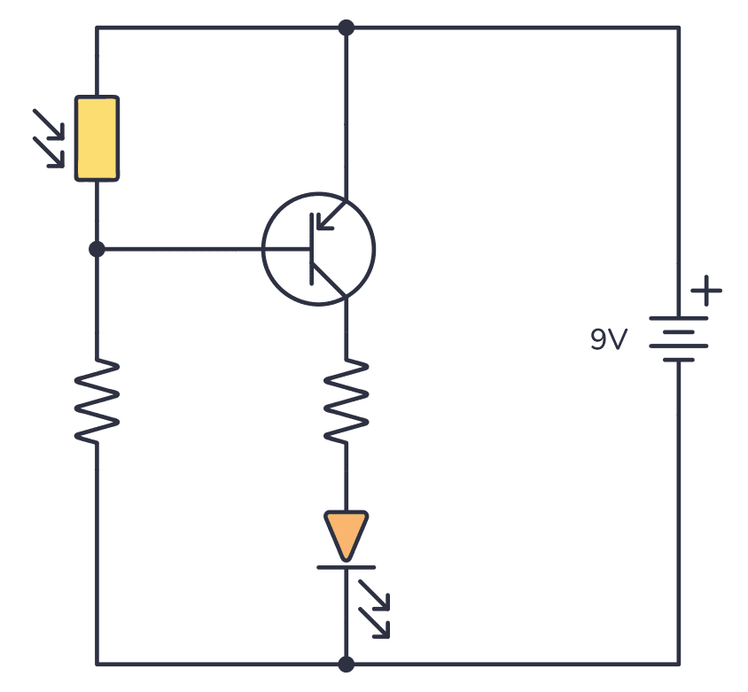
Example: PNP Transistor Circuit
Let’s see how to create a simple PNP transistor circuit. With this circuit, you can turn on a light-emitting diode (LED) when it gets dark.
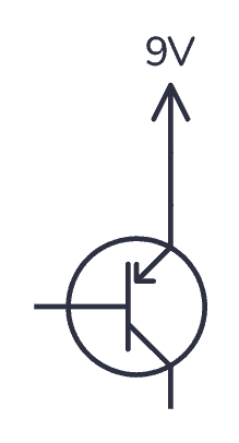
Step 1: The Emitter
First of all, to turn on the PNP transistor, you need the voltage on the base to be lower than the emitter. For a simple circuit like this, it’s common to connect the emitter to the plus from your power source. This way, you know what voltage you have on the emitter.
Step 2: What You Want To Control
When the transistor turns on, the current can flow from the emitter to the collector. So, let’s connect what we want to control: An LED. Since an LED should always have a resistor in series with it, let’s add a resistor too.
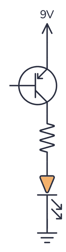
You can replace the LED and resistor with whatever you want to control.
Step 3: The Transistor Input
To turn on the LED, you need to turn on the transistor so that the channel from emitter to collector opens. To turn on the transistor you need to get the voltage on the base to be 0.7V lower than the emitter, which is 9V – 0.7V = 8.3V.
For example, you can now make the LED turn on when it gets dark by using a photoresistor and a standard resistor set up as a voltage divider.
The voltage on the base won’t behave exactly as the voltage divider formula tells you. This is because the transistor affects the voltage too.
But in general, when the photoresistor value is large (no light present) the voltage will be close to 8.3V and the transistor is on (which turns on the LED). When the value of the photoresistor is low (a lot of light present) the voltage will be close to 9V and turn off the transistor (which turns off the LED).
What Controls The Base Voltage?
You might wonder: “How did the photoresistor and resistor on the base magically create the correct voltage of 8.3V when it’s dark?”
It’s partly because the emitter and base makes up a diode. And a diode always try to get its diode voltage over itself. This particular diode has a diode-voltage of about 0.7V. And 8.3V is 0.7V less than 9V.
But, it’s also partly because the size of the photoresistor and resistor on the base sets up the voltage to be in the correct range.
Check Out My Circuit
Here’s a video of the circuit in action:
The transistor I used in this video is a BC557 PNP transistor. It’s one of the transistors that James Lewis recommends in his article on the best 4 transistors to keep in your parts kit.
The photoresistor I used has about 10 kΩ when it’s light and 1 MΩ when it’s dark. The resistor on the base of the transistor is a 100 kΩ resistor. The LED is a standard output LED. And the resistor in series with the LED is 470 Ω.
If you have any questions or comments, let me know in the comment field below!
More Transistors Tutorials

Get Our Basic Electronic Components Guide
Learn how the basic electronic components work so that circuit diagrams will start making sense to you.
