A multimeter is a tool you’ll be using a lot when building electronics. For troubleshooting, testing batteries, and a variety of other tasks.
In this tutorial, you’ll learn how to use a multimeter to measure current, voltage, and resistance.
Multimeter Basics
A multimeter is divided into three main parts:
- The LCD display
- The dial
- The ports

The LCD display shows you the value that you are measuring. The multimeter dial allows you to select what you want to measure. And the ports are where you connect your test probes.
There are usually 3 or 4 ports on every multimeter. And their markings will tell you what they are for. Typical markings are:
- 10Amax – this port is used to measure exceptionally large currents up to 10A.
- COM – always connect the black probe to this port as this is your multimeter’s ground.
- mAVΩ – this port measures voltage, resistance, continuity, and lower currents. On some multimeters, you can also measure other things like diode current, temperature, or capacitance.
How To Measure Voltage With a Multimeter
Start by getting your multimeter ready to measure voltage: Connect the black probe to the GND port and the red probe to the port marked with a V (for Voltage). On the dial select a V range for voltage measurement. The number you see on the dial is the highest value you can measure with that range.
As you can see, there are two options available: DC (direct current) and AC (alternating current) voltage.
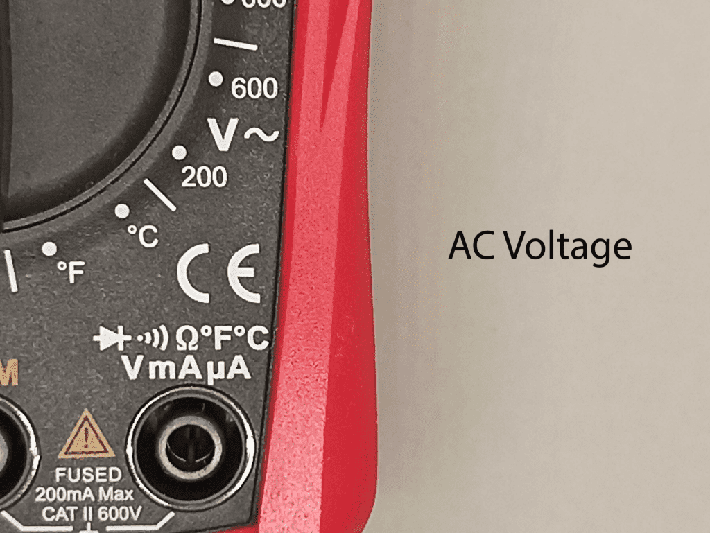
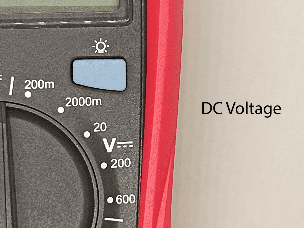
So, before you begin taking a measurement, you must first determine which type of voltage you want to measure and select the appropriate option (almost all low-voltage electronics use DC).

Get Our Basic Electronic Components Guide
Learn how the basic electronic components work so that circuit diagrams will start making sense to you.
Example: Measuring the voltage of a 9V battery
A 9V battery isn’t always exactly 9V. When it’s new, it can be a bit higher. When it’s old and used, it can be lower. So let’s measure the voltage of one.
Plug the black probe into the GND port and the red probe into the port marked with a V. We’ll go with DC voltage for the battery, and for the range, we’ll go with 20V, based on the voltage value we expect:

Measure the voltage by touching the black probe to the negative side of the battery and the red probe to the positive side. The voltage of the battery will appear on the screen:

Experiment by seeing what happens when you swap the probes around. Ideally, you should see the exact same value, just with a minus sign in front.

Also, see what happens when you change the range value. If the multimeter reads 1, it’s overloaded. You will need to try a higher mode such as 200. If the multimeter reads 0.00 or nearly zero, then you’ll have to lower the range.
You can use the multimeter to measure the voltage across components in a circuit too. Just place one probe on each side of the component that you want to measure.
How To Measure Current With a Multimeter
This one is a little tricky because you must interrupt the circuit. But once you see how it’s done, you’ll see that it’s not that hard after all.
To get your multimeter set up for measuring current, you have to connect your red probe to the port for measuring current.
If you’re looking for small current values, plug the red probe into the port marked mA (milliamperes). For larger currents, plug it into the 10A port. (On some multimeters, you’ll see other values, like 20A).
The black probe should be connected to the COM port as always. Turn the dial to the A (current) section and select a number based on the appropriate range.

To measure current, you must connect the multimeter in series so that the current flows through the multimeter. In practice, this means you have to physically interrupt the flow of current and put the meter in-line in the circuit.
Example: Measuring the current of an LED
An LED needs a resistor in series to set the current flowing through it to a certain level. But how do you verify that your resistor selection gives you the current you want?
Let’s connect the following circuit and measure the current flowing in it:


In this circuit, we’re using a 2.5V LED. Since the power supply is 5V, it means we have 2.5V across the 220Ω resistor too. From Ohm’s law, we can find that the current is 2.5V / 220 Ω =
11.36 mA.
To measure the current, we must interrupt the following circuit and insert the multimeter in-line, as shown in the schematics below.

In the photo below, we’ve interrupted the circuit between the resistor and minus (ground) and connected the multimeter instead. We’re using alligator clips instead of the standard pointy probes to get a good connection (using banana-to-alligator cables).

The multimeter reads 11.65 mA, which means that is the amount of current flowing through this circuit.
Measuring current may be difficult at first, but with a bit of practice, you’ll master it in no time.
How To Measure Resistance With a Multimeter
To get your multimeter set up to measure resistance, connect the black probe to the COM port and the red probe to the port marked with Ω. Select the resistance option marked on the dial, and choose the range you think your resistor is within.
To measure resistance, simply place the probes across the resistor. This is particularly useful if you find it hard (or inconvenient) to read the color codes on the resistor.

Example: Measuring the resistance of a resistor
Let’s try to measure the resistance of a 220 Ω resistor.
Note that if you want to measure the resistance of a resistor, you need to (in most cases) remove it from the circuit. Otherwise, the other components in the circuit can influence the reading.
Since we’re expecting 220 Ω, the 200 range is a bit too low. So choose the 2000 range. Then place a probe on each side of the resistor to measure.

The meter will display one of three things, 0.00, 1, or the actual resistor value.
- In our case, the meter reads 221, which means this resistor has a value of 221Ω
- If the multimeter displays OL, it’s overloaded. You will need to try a higher mode such as 20k.
- If the multimeter reads 0.00 or nearly zero, then you’ll have to lower the mode to 200Ω.
Questions?
Do you have any questions about using a multimeter? Let me know in the comments section below!
More Circuit Building Tutorials

10 Simple Steps to Learn Electronics
Electronics is easy when you know what to focus on and what to ignore. Learn what "the basics" really is and how to learn it fast.
Good article. I have another good one which has more information about how to use a multimeter. I want to share it here.
https://mega.nz/#!JrpXESCB!eWfml02MNRB6sAWWbSmHhLsM-FY-aej6lho0kvTqnQQ
Can I measure capacitance of a capacitor mounted in a circuit using a multimeter?
No, you can’t. You need to take the capacitor out of the circuit to make sure the rest of the circuit isn’t affecting your reading.