Electric current is what you get when electric charge moves around a circuit. It’s pretty simple when you finally get it. But there are some common pitfalls that can give you the wrong idea when learning.
And if you don’t know what current is and how it works, it’s a huge source of confusion when learning electronics.
My goal is that after reading this article, you’ll understand what current is. And you’ll understand that a resistor must have the same amount of current going into it as going out from it.
The Current in a River Metaphor
Electric current is the movement of electric charge. It’s not the charge itself.

As a metaphor, you can think of a river. If a lot of water moves past a point in the river, it means the current is strong. If the water stands almost still, it means the current is weak.
(And if there’s no current at all, it doesn’t mean there’s no water, it just means that the water doesn’t move.)
The circles in the animation below represent electric charge. The current isn’t the circles, but the speed of the circles.
So if you look at the speed of the circles at any point, you’ll find the current at that point.

Get Our Basic Electronic Components Guide
Learn how the basic electronic components work so that circuit diagrams will start making sense to you.
(I’ll touch upon the direction of current a bit further down.)

Electric Current Isn’t “Used up”
The battery’s voltage is what pushes the charges around the circuit. And here’s an extremely important fact:
A circuit is always completely filled with electric charges. Even when there’s no battery connected.
But when there’s no battery connected, they’re not moving – so there’s no current. But they are still there.
At the moment you connect the battery, the charges start flowing. And what’s very important to notice is that they start flowing in the whole circuit – not just at the start.
So you’ll have current everywhere in the circuit at the moment you connect the battery.

The battery always receives back what it pushes out. One charge pushed out of the plus terminal means one charge is pulled back in from the minus terminal.
That means that the current flowing out of the battery is exactly the same as the current flowing back into the battery.
Current is never “used up”.
How The Resistor Reduces Current
Let’s have a look at what this means for the resistor.
The resistor will “resist” the current. Meaning that it will slow down the charges flowing through it.
But since the circuit is completely filled with charges, that means the charges are slowed down in the whole circuit.
Just like when you squeeze a garden hose so that less water flows out of it. The water is slowed down in the whole hose, not just after the spot you squeeze.
So the current before the resistor is equal to the current after the resistor.
This means that in the case of using a resistor to protect an LED – it doesn’t matter if you place it before or after the LED. In both of the circuits below, the resistor protects the LED:

Electric Charges Don’t Accumulate Anywhere
Sometimes after explaining the above two circuits, I get this question:
“But Oyvind, what about in the beginning when you connect the battery? Before the charges have accumulated in the resistor, surely the LED will get a high current at first, right?”
No. The charges never accumulate anywhere in the circuit.
Remember that the circuit is always completely filled with charges. One charge pushed in means one charge pushed out.
This means that the current flowing out of the battery is the same as the current flowing into the battery, also at the exact moment you connect the battery.
The Direction of Current
In the animations above, the current flows from plus to minus. But you might have come across information saying the opposite – that current really flows from minus to plus. What’s correct?

Electrons flow the opposite way, from minus to plus. Electrons carry a negative charge and are the particles that usually move inside wires.
But current isn’t defined as the flow of electrons. It’s defined as the flow of charge.
The electron carries a charge. But there are other particles that carry charge in a circuit too. For example electron holes that move from plus to minus. And they can both exist in the same circuit.
Electrons are the most common particle that flow in an electric circuit. So shouldn’t we say the current flows from minus to plus?
Well, you can. But remember that electrons carry a negative charge. So you’ll end up with a negative current. Which is fine. You’ll get the same results as us who prefer the plus to minus direction.
Just know that in the world of electronics, an electric current of -20 mA flowing from minus to plus is the exact same thing as a current of +20 mA flowing from plus to minus.

Questions
After reading this, is it clear to you what electric current is? Do you have any questions? Let me know in the comment field below!
More Basic Electronics Tutorials
Get Our Basic Electronic Components Guide
Learn how the basic electronic components work so that circuit diagrams will start making sense to you.

Nice, as always.
For great animations, you might want to check out Eugene Khutoryansky
‘s animations on YouTube.
There are som really nice videos there. Thanks for the tip!
Have been automotive technician for many years. Wanted to learn more about how the electronic circuits work. Leaning many aspects of circuitry through your teaching. Can’t afford to subscribe, but wish to thank you for what you have shared. Thankfully yours racenut 157.
That’s great to hear, Gary!
Brother I would like to learn more about electronics I really enjoy your lessons like this one of current today but basically I need to understand electronics more because am an electrician now I want to go deep into electronic circuits set ups and designs.
Great, keep at it!
Very concise explanation. It will help me build and diagnose circuits.
Thanks Al Reiser
Great=)
This is massively helpful! Could you consider adding something about how it’s possible to slow the current in just one part of the circuit? Say for example an LED is activated by a switch and that section of circuit, once connected, has a resistor slowing it. How does that not effect the rest of the circuit? I feel like the penny has almost dropped! 👍
Glad to hear it helped, Rich!
Let’s say you have the circuit with resistor and LED above. Then you add another resistor and LED in parallel to what you already have. This added branch of resistor+LED will not affect the original branch.
Thank you for that simple response to Rich’s question. The “original branch” concept really helps me understand.
Charges are moving to have current, it’s ok. But, what happen to electrons do they move at all, or just shaking? And, please tell me what is the speed of charges, as well as the speed of the electrons?
Yes, they move. Electrons carry the charge so if they would only shake, the charge would only shake too.
The speed of charges is the current that flows. If enough charge carriers flow past a point per second to make up 1 coloumb per second, that would give you 1 ampere (A).
Speed of electrons: https://education.jlab.org/qa/electron_01.html
Please can you explain the understanding of the AC current as you did it for DC?
Here’s a place to start: https://www.build-electronic-circuits.com/difference-ac-vs-dc/
“But Oyvind, what about in the beginning when you connect the battery? Before the charges have accumulated in the resistor, surely the LED will get a high current at first, right?”
No. The charges never accumulate anywhere in the circuit.
False! You talk as if there are no capacitors, and you imply that the electric field (=voltage) travels at infinite velocity, when in fact it is it is travelling in vacuo at only 300 000 km/s, and even less in matter. In some materials, preferred to use as dielectric in solid state capacitors, the velocity of light may drop to just a few hundred kilometers a second!
In terms of your water analogy, to make water flow in a river, there has to be a drop in height (=voltage) from start to finish. If there is a (=capacitor !) in between, it will halt the flow of water, until the sluice is overflowing and the height difference asserts itself again as the driving force for the current.
If your statement were true, RC resonators could not exist, and that means computers, or TV, radio or cellphones would be impossible, as the existence of electric waves relies on a finite velocity of light.
Even with capacitors the current going into it is the same as the current flowing out of it. The capacitor does not store charge. You can read about it here: https://bit.ly/39pECMZ
But as current flows through the capacitor, the voltage across it rises. The time it takes for the voltage to reach a certain point is what gives you delays in a circuit, which is what RC circuits depend on.
The capacitor in the water analogy is a container with a rubber membrane inside. Here’s a nice article for that: http://amasci.com/emotor/cap1.html
I am disappointed. I had assumed that part of the training an Electrical Engineer like you has received does include that it does take time for information to travel, i.e. that the velocity of light is finite. When you switch on power and make a current flow, one side of that switch will know that it is open a short moment before the other side learns about it. During that short time interval, you have alternating current (AC), and the current flowing on each side of the switch is different. But if you make that interval long enough, what happens during that short interval becomes negligible, and you may state that in-going current is the same as out-going current. Important here is to realize that in-going = outgoing is true only for DC (discrete current), i.e. there are no switches, transistors, capacitors or inductors in the circuit. If there are, they behave the same as as resistor, having near zero resistance if closed, and near infinite resistance if open. A capacitor, in a true DC circuit, i.e. in a circuit where current does not change with time (or, in mathematical terms, if dI/dt=0), a capacitor acts as if it were an open switch, and an inductor as if it were a closed switch – only their ohmic properties count.
If you can handle calculus, you’ll know that at the time of closing the switch, dI/dt0, i.e. the current changes, and it changes differently on both sides of the switch, just because it does take time for the to learn about the status change.
Since you are at war with the velocities applicable inside a circuit, allow me to quote https://en.wikipedia.org/wiki/Electron#Conductivity: “Because of collisions between electrons and atoms, the drift velocity of electrons in a conductor is on the order of millimeters per second. However, the speed at which a change of current at one point in the material causes changes in currents in other parts of the material, the velocity of propagation, is typically about 75% of light speed. This occurs because electrical signals propagate as a wave, with the velocity dependent on the dielectric constant of the material.”
Wikipedia here uses a more precise terminology than I did above, drift velocity is the speed with which the charge carriers (electrons in a metal wire, the atoms do not move at all) move, velocity of propagation is the speed by which the electric field travels, and light speed is the speed by which the electric field travels in vacuo.
The relationship between velocity of propagation and light speed is
(velocity of propagation) = (light speed)/(square root of kappa) https://en.wikipedia.org/wiki/Velocity_factor
and values for kappa you may find in https://physics.info/dielectrics/
For potassium tantalate niobate, kappa is listed as 34000, which gives 1.6km/s for the velocity with which an electric field propagates in such a high-powered dielectric, much, much slower that its velocity in vacuo.
Perusal of the same table shows that common insulators have kappa values around 2, and thus fit perfectly with the quotation given above.
Please get your facts right, khanacademy.org is not a trustworthy source.
I don’t disagree with your facts. I’m sure they’re all correct.
I’ve also learned about the speed of propagation at some point in time. But I’ve never had to use that knowledge for designing circuits. So I disagree that those facts are important to learn for someone who wants to learn to design and build electronic circuits (which is the intended audience for this article).
A wire does not have 0 resistance, but for most practical purposes you can assume it has. Same with current. For most practical purposes, you can assume the propagation speed is infinite. And my personal belief is that these simplifications are especially important when someone is learning a new concept.
But that said, I really appreciate you sharing your knowledge about the speed of propagation for those who want to look into the details of what happens on a particle level.
All the best,
Oyvind
Ahh . . . Making (some) progress. You accept now that the velocity with which charges are transported can be changed. Excellent!
Now, go back to your picture of charges moving in a DC circuit. Widen the wire at some place, make it, say, twice as wide. Let’s call that wider wire a balloon. What is the current in the balloon? Now you need to consider two situations:
1. the balloon is completely filled with charges. Under these circumstances there are twice as many charges, but they move at half the velocity. Since current is charges moved per second, the current stays the same.
2. Not so if the balloon is empty or partially empty. Then charges move into the balloon, but do not come out. You have current on one side of your circuit, but not on the other side. This situation is called AC or alternating current, the naming being chosen for historical reasons.
In a circuit, the balloon can be any device capable of storing energy, such as a battery, a capacitor, a inductor (coil), or a rotating motor. Obviously, if the balloon is made out of rubber, you can close its entrance, and expect current to flow out the other, still open side. In a motor, this is called the back-emf of that motor. In a capacitor, this stored charge (another name for stored charge is static electricity), as it is can hurt you badly if you inadvertently touch it, and when building circuits, you better be aware there are many situations where static discharges will destroy your circuits.
This stored energy is called POTENTIAL ENERGY, because you can make use of it at will, unlike KINETIC ENERGY, which you can no longer utilise the moment its carrier is past you.
You can of course quote Kirchhoff’s rule, but you do need to emphasize that it is valid only for DC circuits, i.e. where energy storage components such as capacitors, (chargeable) batteries, and others are not present.
Your article is not constructed in such a way that this is clear for any reader, including those, like me, who do know thermodynamics.
What you should have made clear is that the proper version of Kirchhoff’s rule is
in=storage + out, and not
In = out.
By omitting that storage can and does take place, you have produced an article that is factual in places and utter rubbish in others, thus making it un-trustworthy and misleading your readers.
Example: “A circuit is always completely filled with electric charges.” Are there (movable) charges in the dielectric of a capacitor? Of course not. Charges do not move through a capacitor, they only move in or out, that’s what a capacitor is all about. Triboelectricity, and its technical application, the van der Graaf generator, are other means to remove charges from a circuit.
The article should be completely re-written, since as it stands it is rubbish. If you want my help in doing so, you may contact me privately.
Theoretically you’re right but it will in no way help those that are just starting to put one or two components together, so please stop
I agree with Dandy. Your explanation may be completely on point Wolfgang, it is however fully incomprehensible for people (like me) trying to learn about electronics and electronic circuits. And that is the main focus of these e-mails and the Ohmify website. Your lectures are more suitable for trained pro’s and electronics/physics students. Something the average audience over here is clearly not.
AC current should be scrapped and tossed in the rubbish heap. Its harmful to all life. We are going to switch to DC and self generating power systems for our homes that cause no harm. Mark my words. This is the reason Im learning electrics. Im going to make it myself. Go back to the 1900s and learn from the real masters.
I also do not like the water analogy for electrical/electronic circuitry! In my opinion it only works properly when you consider proper hydraulic (closed) systems. However, Oyvind, in an effort to simplify the theory and make it as easy to understand as possible, has deliberately stayed away from all the issues you have raised!
If you don’t understand why it is important to keep things simple for the benefit of new learners then you ought to set up your own website with a view to teaching more advanced practitioners!
Electrical and electronic engineering comes easily to so few of us! The majority have to work hard and really struggle to make the mental leaps that the subject demands!
Nit picking at silly and inconsequential points is not helpful to anyone!
I hope that at some moment in your career you have the opportunity to educate the new generation. I think you will wish to return here and delete this comment!
Kind regards,
Scott Reid.
HNC Electronic Engineering 1997 (South Lanarkshire College, East Kilbride, Scotland)
Domestic Electrical Installer 2017 (Erudite Training, Manchester, Lancashire)
Requirements for electrical installations 17th Ed (C&G 2382), 2017 (Erudite Training, Manchester, Lancashire).
Inspection and Testing of Electrical Installations (C&G 2392) 2017 (Erudite Training)
Requirements for electrical installations 18th Ed, (C&G 2382) 2019 (SETA Stockport)
Inspection and Testing of Electrical Installations (C&G 2391) 2020 (Erudite Training)
In-service Inspection and Testing of Electrical Equipment (5th Ed) 2021 Erudite Training).
Electrical Vehicle Charging (C&G 2919) 2021, (Erudite Training).
I have worked in the electronic and electrical industry (manufacturing, commisioning, fault-finding/repairing) since 1997! Now that I am teaching in this field, I have never been so busy! Nor have I ever felt so useful or so valued! Having the opportunity to try and pass on the knowledge and experience I have gained over 25 years is a priveledge that few practitioners of our craft ever have the honour to fulfill!
Hello
Can you please explain how to test circuits with meter so beginners can do practical testing on your theory explanations.
Great Work.
Thankyou for sharing knowledge.
Yes, that’s definitely an article I will write at some point. Thanks for the tip!
That sounds like a great idea, Warren Ferguson! Thanks for being open to the idea, Oyvind. I’ll look forward to that one.
Thank you so much for this simple to understand concept. I’d often wondered (worried) about where in the circuit you described with the LED, to put the resistor. Now it all makes sense. Thank you, and well done.
I’m glad to hear this helped! That’s what motivates me to keep writing.
This is awesome! It’s short enough that I can deeply focus on it while still being long enough to present the topic well. This is a great help to me. I learn best by visualizing a representation of what is going on versus just being told what is actually happening. Thanks!
I’m very happy to hear that!
I agree with Dandy. Your explanation may be completely on point Wolfgang, it is however fully incomprehensible for people (like me) trying to learn about electronics and electronic circuits. And that is the main focus of these e-mails and the Ohmify website. Your lectures are more suitable for trained pro’s and electronics/physics students. Something the average audience over here is clearly not.
Very good explanation. One of the things I like about electronics is this organic quantum understanding.
Thanks!
Current is the speed of the flow of charge in the circuit, so if we connect a resistor in the circuit it will reduce the speed of charge-“current” in the entire circuit. This is what I got from this, am I corrrect?
Yes, that’s correct.
Oyvind,
I’m not sure that’s entirely accurate. It’s my understanding that resistors decrease the number of electrons in the circuit but the electrons still flow at the same speed.
Jim
That’s true, Jim. Electron speed stays the same.
But if we don’t think about electrons, but instead the charge (Coloumb) that these electrons result in, then we can simplify a bit.
One ampere is equal to one coulomb passing a point in a wire in one second. Two ampere would be two coloumbs passing in one second. The more coloumbs that pass per second, the higher the current. So although not representative of the speed of the electrons, it’s one way to wrap your head around currents.
Animations look great! So the current is the same everywhere in the circuit. Can you explain the voltage divider this way?
Thanks! I’m still learning about animations, but starting to get the basics now:)
I should have mentioned (and will add it later) that this goes for series circuits.
The voltage divider is two resistors in series. Both will have the same current through them.
The output voltage of the voltage divider is the voltage across the second resistor.
The voltage across any resistor is given by Ohm’s law: Voltage = Resistance x Current.
So a certain current through a resistor with a certain value will always give the same voltage drop.
Not sure if this analogy stands. Consider a “Freeway” (in US/Australia) or a “Motorway” (in UK). Cars speeding at 65 MPH (approx. 100 KMPH) the speed of the cars is the current (amp), the power of the engine (in HP) is the volt and the force exerted by car/vehicle is the watt.
I am just beginning the study of this great subject of electronics. I thort it was going to be a struggle, but I was wrong. Thanks to great instruction from teachers like Oyvind I not only am understanding but am having fun. I also am grateful to students who put their queries and practical experiments online – reading their problems helps my understanding too.
Keep it up guys – you’re all doing a great job!
Tony
Thanks a lot, Tony! That’s really great to hear =)
Let assume you want to use resistor for a circuit, how do you know the exact resistor to use for the circuit?
It depends on the circuit. If you have a specific circuit, I can give a specific answer. But the general answer is using Ohm’s law.
Admin had a great answer to your question but you might also want to use the 1 : Ohms law calculator but it won’t be helpful if you do not already understand 2 : Ohms law.
Here are websites matching the numbers above:
1 : http://www.ohmslawcalculator.com/ohms-law-calculator
2 : https://www.build-electronic-circuits.com/ohms-law/
Finally, that makes so much sense. I didn’t know a resistor after the LED would work. That’s pretty neat!
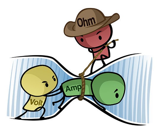
I love the first picture about volt-guy trying to shove amp-guy through the pipe being constrained by ohm-guy. It really helped me conceptually. Thanks!
My problem with the animation you are referring to is that there is that the circuit is empty after that bottleneck point in the circuit that he is squeezing through. Shouldn’t it show charges in front of the one being squeezed through?
You are absolutely right.
If I understand ,the resistor is not a load just a slower device.
What happend if we put a second LED load in that circuit instead of a resistor?
If you place a second LED, you get a voltage drop of two times the forward voltage of the LED. For example 4V for a two 2V-LEDs. The rest of the voltage drops across the resistor. If you don’t have a resistor, more voltage drops across the LEDs and they are likely to break.
Well according to the theory of older books on electricity, current is the flow of electrons and of course these books were more physics oriented. However i have been following more modern reseach on currunt that is inline with your lessons. I suspect that in the future current may be defined differently. Example current used to flow in one direction, now it flows both ways.
I would like to join to help the members, but do not want to pay. Is there a contributor/instructor signup?
Hi Mike,
Do you mean for Ohmify? We don’t have that. But you are welcome to write to us and tell us a little about yourself and see if there is a way to cooperate: https://ohmify.com/contact
That was a great explenation. As a beginner, it was super easy to understand. Thank you
Thanks a bunch, very useful for beginners to understand.
There is a question. Does the electric current from plus to minus mean proton carries charge?
Cheers,
William
Hi William, the particles that are moving in an electric circuit are mostly (but not always) electrons that move from minus to plus.
You can see a list of some other charge carriers over at Wikipedia: https://en.wikipedia.org/wiki/Charge_carrier
(Proton conductors is on the list)
But remember that no matter what is flowing on the particle level, it results in a positive electric current flowing from plus to minus (or a negative electric current flowing from minus to plus if you prefer).
Thank you so much sir, am in Uganda & I really want to learn how to repair electronics devices but reading through your email is really helping. Though I still lack the funds for subscribing, I know with time I might be able to do so. From the bottom of my heart, thank you
I could understand that the Current is never “used up”. Electron never be destroyed. If it is correct than how work is done and how consumption of electricity is measured by an energy meter. How electric energy work done is possible with out the destruction of electron? I want to know more about this my confusion.
With best regards to my teacher,
Super clear, thanks! Do you have a similar article explaining voltage?
Not really… But the simple explanation is that voltage is the force that pushes the electrons around the circuit.
Hi,
Great explanation. But I have a query as you said the voltage a battery pushes the already present charges in the circuit and battery loses a charge from negative but it gets one from positive side. Why does battery then gets discharged.
Please explain.
Thanks
A battery has a surplus of electrons on one side and a lack of electrons on the other side.
The electrons don’t want to be where there is a surplus. They really want to go over to the other side where there is spare room for them. But there is not path for them to take inside the battery to go over to the other side. The only way for them to go to the other side is through whatever circuit you connect to the battery.
So when you connect the circuit to the battery, they start to flow over to the other side through the circuit. When all the electrons have gone over to the other side of the battery the battery is discharged. Th current stops flowing because there is no more surplus electrons on one side of the battery.
I love these Barney Style explanations! I wish I’d discovered your site a long time ago!
Brother these comments go wild. We are in basic electronics. Every Electrical Engineer knows that electricity flows negative to positive. Ben Franklin said that electricity was like a water falls so it flows from the top (Positive) to the bottom (Negative). So in physics they teach electricity flows positive to negative. (we know better). A coulomb is defined as 6.24 X 10 -18 of electrons. One coulomb pass a given point in one second is one amp. Whether the wire is 24 gauge (small) or 14 gauge (large) it doesn’t mean anything.
The atomic make up of copper, silver, gold, and a few others make them good conductors. What happens is that the battery introduces an extra electron (negative value of the atom while protons are positive). the copper atom easily picks up this extra electron, but now has too many electrons. So it reject an electron so it is balance again and that electron now moves to the next atom, which in turn has one too many and the process is repeated and we have electric flow. Now let’s add some values to the circuit. 12 volt battery, and a LED. Now the LED is the key here as it wants 20 ma and has a voltage drop of 2 volts (this varies with the type of LED). Now with 12 volts applied and 2 volts dropped by the LED use we need a resistor to drop 10 volts or the LED will burn up. We know the current 20 ma. so we have 10 volts / 20ma = 0.02 amps= 500 ohms. If we added a second LED in line we would have the first one dropping 2 volts at 20 ma and the second one dropping 2 volts at 20 ma so the current to run two is the same as one but we now are dropping 4 volts. so we need a different resistor. 12 volts – 4 volts = 8 volts. 8/.02 = 400 ohms.
In a simple circuit like this the current is the same everywhere, in the wire through the switch through the resistor and the LED.
There is no AC. AC out of your wall goes plus 110 to negative 110 60 times a sec. (60 hz). Dropping the switch has the circuit go from 0 to 12 volts that’s not AC.
I would like Wolfgang Vogelbein to contact me and explain why no one is manufacturing and selling lithium phosphate batteries for use in propelling electric vehicles. I have a 2000 Ford Focus conversion and can’t find any batteries (maybe lead acid) for my 144-volt system. And if he replies that there are none available, how does he suggest that I power my vehicle? Lead acid is too heavy, doesn’t have the range I need, and doesn’t last. I don’t care how sarcastic he gets if he can actually provide me some useful information.