A breadboard is a simple and useful tool for connecting a circuit. It’s really useful for beginners as you can easily experiment and test out circuits without soldering. But it’s also useful for more experienced people since you can prototype an idea, or parts of a circuit, quickly.
I often use breadboards in my work.
Want a quick introduction to the breadboard? Check out my short video below (2:30) or continue reading.
How To Use A Breadboard
The breadboard has internal connections between its holes. Some vertical connections and some horizontal connections.
Normally, you use the columns on the sides to connect your power supply. And you use the rows in the middle to connect your components.
Power Supply Columns
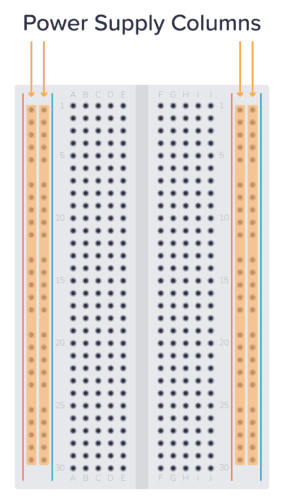
It’s common to use the columns on the left and right for connecting the power supply. These columns are connected vertically. So, if you connect 5 volts to the top hole of one of the side columns, you will have 5 volts in all the holes of this column.
Use the columns marked with a red line for plus, and the column marked with a blue line for minus.

Get Our Basic Electronic Components Guide
Learn how the basic electronic components work so that circuit diagrams will start making sense to you.
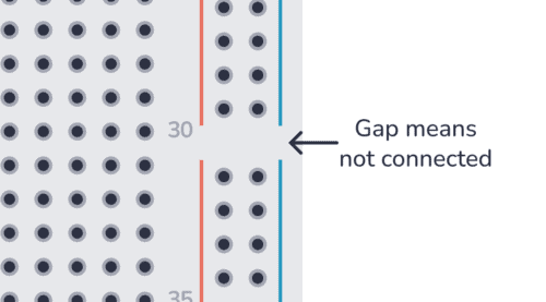
Note: Some larger breadboards are split into two so that the upper half is disconnected from the lower half. This is indicated by the vertical blue and red lines being split in two.
Component Area
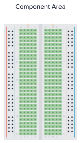
In the middle of the board, you’ll find the component area. This is where you normally connect your components. Here, the holes are connected horizontally, in rows. And the left side is separated from the right side.
This means that the pins of your component must be on different rows, or on different sides of the board. Below you can see two ways to connect a resistor:
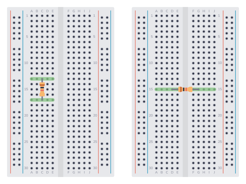
To connect something to either pin of the resistor, you need to connect it to one of the rows marked in green.
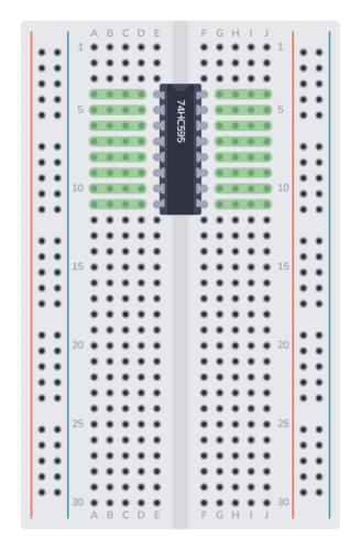
If you want to connect a chip, you need to connect it across the gap in the middle. Then, to connect something to one of the pins, use the holes marked in green:
Example Breadboard Circuit
Here’s a simple circuit diagram of a resistor and LED connected to a 9V battery:
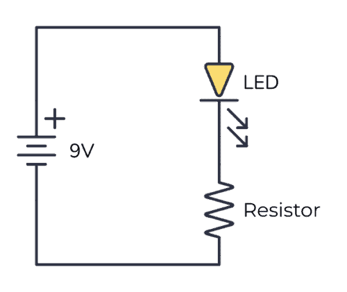
To connect this circuit to a breadboard, first connect the resistor, making sure the pins are on different rows. Then connect the LED, making sure its negative leg is connected to the same row as the upper leg of the resistor.
This is such a simple circuit, that it’s not necessary to use the power supply columns. You can connect the battery directly to the component area. Here’s the complete circuit with a resistor and LED connected to a 9V battery on a breadboard:
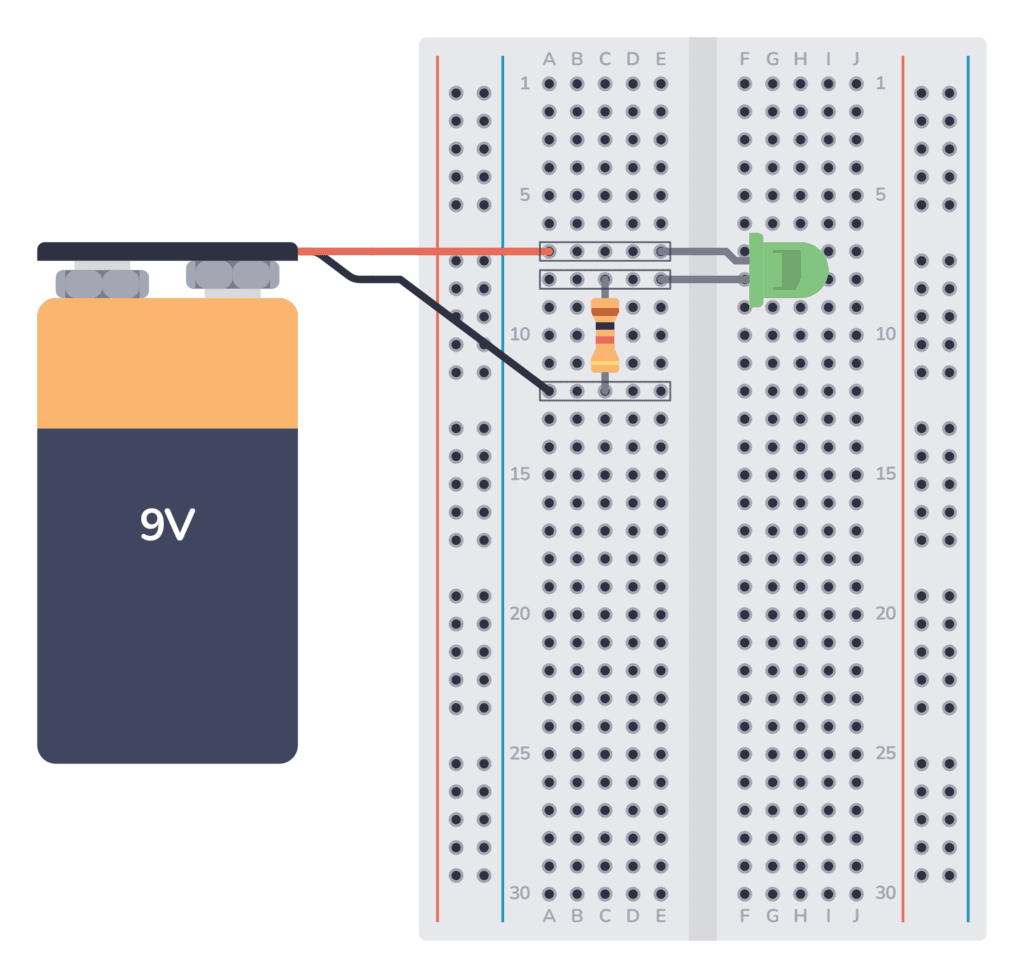
In the circuit above, I used three rows:
- The upper row connects the plus of the battery to the positive leg of the LED.
- The middle row connected the negative leg of the LED to the upper leg of the resistor.
- The lower row connects the lower leg of the resistor to the minus of the battery.
Best Wire Thickness to Use on a Breadboard
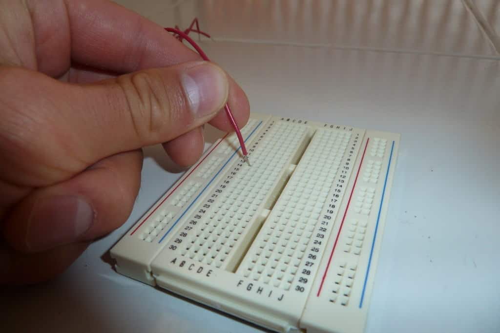
Not all wires work well with breadboards. In my experience, the best wires to use are 22 or 23 AWG single-strand wires. Single-strand means the wire has one solid core inside (as opposed to lots of tiny wires wrapped together).
AWG stands for American Wire Gauge. And 22 AWG means a diameter of 0.65 mm. And 23 AWG is 0.57 mm.
For other basic components, buy them with a leg thickness of 0.5-0.7 mm for the best fit. Most through-hole components will fit in a breadboard, but I’ve come across components with legs that are too thick to fit, or too thin to give a good connection.
What Can You Build With A Breadboard?
Breadboards are often used to build a prototype or to test a circuit. Or a part of a circuit that you are unsure about.
For example, let’s say you wanted to build a microcontroller circuit that controlled relays with the output pins from the microcontroller. Then you would want a little driver on the output. If you are unsure about this driver circuit, you could throw it together on a breadboard quickly to make sure it works before you put it into your final design.
Or if you are learning about circuits you will come across a lot of little circuits that you want to test. Connecting these on a breadboard can be really useful. I recommend you test out these circuits to get started:
But you can also use breadboards to build complicated circuits, as long as you have enough space and are comfortable with lots of wire connections.
More Circuit Building Tutorials

10 Simple Steps to Learn Electronics
Electronics is easy when you know what to focus on and what to ignore. Learn what "the basics" really is and how to learn it fast.
