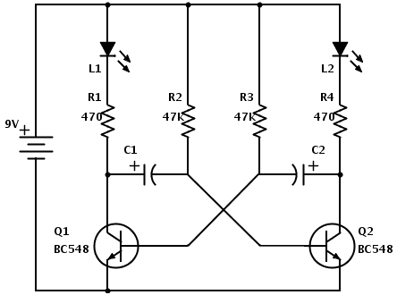
This is my step-by-step guide to schematic drawing in Eagle. Let us say we find the circuit above interesting and want to build a real electronic circuit out of it to test in the real world. The first step is to recreate the schematics in Eagle.
Create new project and schematic
We start our schematic drawing by creating a new project and a new schematic in Eagle. Open Eagle’s Control Panel and choose “File->New->Project” from the menu.
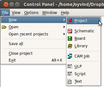
Add a new schematic to the project by selecting “File->New->Schematic” from the menu.You now have a blank schematic ready for drawing.
Add components
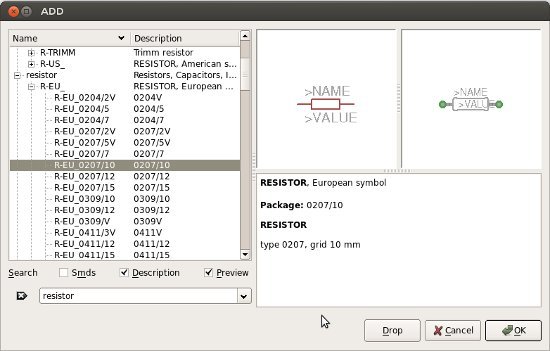
We continue by adding the four resistors to the schematic. Select “Edit->Add..” from the menu in the schematic editor. The “ADD” dialog box appears. Here we want to locate a resistor.
Write “resistor” in the search field and press Enter. You will probably find many alternatives. I chose a through-hole resistor called R-EU_0207/10 from the “resistor”-library. Choose one and press “Ok”.

10 Simple Steps to Learn Electronics
Electronics is easy when you know what to focus on and what to ignore. Learn what "the basics" really is and how to learn it fast.
Place the resistor on your schematic by left-clicking. Do this four times to get four resistors, then press ESC to return to the “ADD” dialog box.Continue to add the capacitors, transistors and LEDs in the same way.
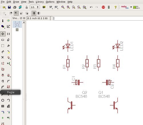
Tips: To place the two transistor as mirrors to one another like I did, use the Mirror function “Edit->Mirror” in the menu.
Add component values
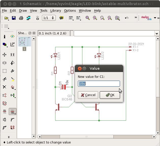
Now we’ll add values to the components. To do this choose “Edit->Value..” from the menu. Then click on the component you want to set value for. Enter the value and press Ok.
Add connection between components
To connect the components we need to add nets between them. Add nets by choosing “Draw->Net” from the menu.
Note: Never use “Wire”, always use “Nets”. The “Wire” does not always create the electrical connection you want.
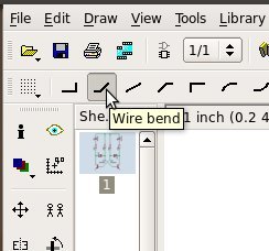
Tips: If you want diagonal lines, choose the second “Wire bend” button from the toolbar.
Add power connection
If you want to create a practicable electronic circuit you will also need to connect power somehow. You can add two header pins for this. Search for “2 pin header” in the “ADD” dialog box to find a suitable part in the “con-molex” library. Add this and connect the two pins to the circuit.
Electrical Rule Check
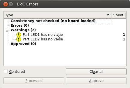
Now we are ready to run an Electrical Rule Check (ERC) to see if there are any mistakes that need to be fixed.
Select “Tools->Erc” from the menu.
When I run it I get two warnings telling me that the LEDs don’t have any defined values. I know that this is not necessary for the LEDs so I click “Approve” on both of them.
Our schematic drawing is now complete.
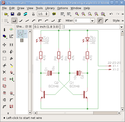
Now, it’s time to create a PCB from the schematics.
Return from Schematic Drawing to Electronic Schematics

Get Our Basic Electronic Components Guide
Learn how the basic electronic components work so that circuit diagrams will start making sense to you.
