Did you know there are many types of resistors?

Your electronic schematic tells you that you need a resistor of 100k Ohms. Ok, so you go to an online store to buy one. But there you get all these choices: Thin film, carbon composition, metal film +++.
“Just give me a freaking 100k resistor man!”, you scream in despair.
Believe me, I know your frustration. It took me a long time to actually bother reading about different types of resistors. So I just chose random resistors for all my electronic circuits. Usually, it worked flawlessly. Maybe I was lucky or maybe I just didn’t identify the resistor as the problem when I had a problem.
Anyway, my aim here is to provide a simple guide on how to choose a resistor without diving deep into details.
Resistor types
Resistors can be made of several different materials and methods. Here are a few types of resistors:

Get Our Basic Electronic Components Guide
Learn how the basic electronic components work so that circuit diagrams will start making sense to you.
- Carbon composition
- Carbon film
- Metal film
- Thick and thin film
- Foil resistor
- Wirewound
The different types have different properties. Some are very accurate, some can withstand high temperatures, some can withstand high power and some are cheap. Some are good for low noise applications, some are good for high-power applications, some for high-speed applications and some for measurement circuits.
If you want to learn more about the specific resistor types, I recommend checking out www.resistorguide.com
Choosing a resistor
So, how do you choose a resistor?
First of all, you need to choose the resistance value. To do that you use Ohm’s law. One common example is to find the resistor value you need for an LED.
Next, you need to consider the power that the resistor needs to dissipate. Power dissipation in a resistor can be calculated with the formula

where P is power in Watt, V is the voltage drop over the resistor and R is the resistance of the resistor in Ohm.
Let us look at an example:
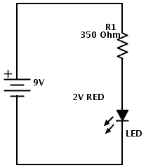
In this circuit, we use a LED with a voltage drop of about 2V. We found that the resistor should have a value of 350 Ohm. The circuit is powered by a 9V battery.
How much power will dissipate in the resistor?
To answer this, we first find the voltage drop over the resistor. Let’s say we use a LED with a voltage drop of 2V. That means the voltage drop over the resistor will be 9V-2V = 7V.
Using the formula for power dissipation, we find P = 7V*7V / 350 Ohm = 0.14 W.
So we need a resistor with a power rating of at least 140 mW. But preferably more.
A rule of thumb is to find a resistor with twice the power rating. Here I would choose a 250 mW resistor since those are the most standard ones.
Usually, you can just use the cheapest resistor you can find with the correct power rating.
When to choose a non-standard resistor?
So why all these different types of resistors that I mentioned before? Because for some circuits the actual type of resistor also matters. These circuits include:
- Noise-sensitive audio circuits
- RF circuits
- High-power circuits
- High-accuracy measurement circuits
- High-speed circuits
Which resistor type to choose for which application is beyond the scope of this article. If you are building any of these types of circuits, see if the schematics specify the resistor type. If not, maybe this article can help you out.
Summary
For most standard circuits, you don’t need to worry about the types of resistors you choose. All you need to worry about is the resistance value and how much power it can take.
If your schematic does not tell you the necessary power rating for the resistor and you don’t know (or don’t want to know) how to calculate it, then try using a standard 1/4W resistor. If it fails after a short while, you should exchange it for a higher wattage rating. Maybe you should even take the effort to calculate a decent value ;)
Do you think it’s hard to choose a resistor? Write your comments and questions below!
Return from Types of Resistors to Electronic Components Online
More Resistors Tutorials

10 Simple Steps to Learn Electronics
Electronics is easy when you know what to focus on and what to ignore. Learn what "the basics" really is and how to learn it fast.
Dear sir’s/madam,
Kindly I want to know about what effect on wattage if we use resistor in series and also parrlle please explained by example….
Waiting your response.
Thanking you.
Hey
The formula for calculating power is the same in parallel and series.
P = I*V or P = V^2/R
P= Power in Watts
I = Current in Amps
V = Voltage in Volt
R = Resistance in Ohms
Cheers!
Oyvind
Why did you go with power dissipation on the first page when we first have to find ohms? Other than that this article helps a lot. thanks.
Hello Tomoslav,I would like to try answer your question.
The reason as to why we went to power desipation rather than finding out the resistance needed is, The guiding point of the value of resistance needed is the end point consumption… LED, My point is, power which must go through the resistance so that the LED can come ON is the division of the squared voltage and Resistance.
Also, if you were to decide on the LED to use having resistance,,,all same.
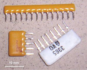
An additional reason for using a non-standard resistor that you don’t mention in this article is implied by the picture you use for that section, which show multi-lead resistor networks.
Typically the resistor networks are a package of resistors where one end of each resistor is connected to a common lead, and the other ends are all separate. A resistor network is especially handy when building an audio mixer, for example, because each input typically has both a potentiometer (to adjust level) and a fixed resistor (for isolation, or to set a maximum input, I guess) for each input.
Using resistor networks in cases like these simplifies wiring for both breadboards and prototype printed circuit boards, and reduces assembly time even for custom PC boards.
Thanks for a good an insightful comment, Mark :)
Cheers!
Oyvind
Provide a bit more info on what is power dissipation ?
It is how much power that is lost from the circuit at that component. Usually in the form of heat.
How can you find out what the power dissipation is?
From the formula under “Choosing a resistor” above: P = V^2/R
Cheers!
Oyvind
could you explain me what is standard and non -standard resistors and also about the tolerance of the resistor?
To learn more in-depth about these things I recommend you check out http://www.resistorguide.com/
Cheers!
Oyvind
Hi there I have a couple of questions for you about resistors with capacitors.
I have a capacitor and I’m trying to use it with a home made water battery. The water battery makes 1.6 V but it drops to 0.1 V when charging the capacitor. So my question is what resistor should I use.
My second question is do you know whether voltage drop is the problem because the circuit worked earlier during testing.
Thanks and have a great day
(Cheers ????)
Hi,
For you first question on what resistor to use, that really depends what you are trying to do.
And I don’t really understand your second question, because I don’t know what circuit you have and what the problem you are experiencing is.
Please explain, and I’ll try my best to give you an answer.
Oyvind
i am searching these details from last three years . finally i got it .thankyou “ADMIN”. have a nice day
Great =)
Oyvind
this is the best article what i have ever read. it solved my every problems. thank you very much and all the best.
The article is fantastic but you did not explain as to how 47ooo ohms converted into kilo ohm (Dividing the figure 47000 by 1000) but what about wattage of 0.14 watts into 140 mili watts (Perhaps by multiple of 1000). Any how a great contribution. All the components in a circuit are mostly not available in every country, hence I am un-able to proceed ahead to make simple circuits (DIY).
Hey Akbar, you can see the conversion from 47000 to 47k here: https://en.wikipedia.org/wiki/Metric_prefix
If you can’t find the components you need I recommend you to buy them online:
https://www.build-electronic-circuits.com/buy-electronic-components/
Best,
Oyvind
Can I know the function of every type of resistor you label above?
That was what I tried to explain in the article…
thanx GOD,,
I found your website,,
i learnd a lot of what i problem before,, more power to u sir.143
Sir
Please tell me how a dc current convert into heat , with circuit diagram and which componenets are used.if we use 12v or 24v battery
Thank you
My first guess as I was reading the article was that some resistors would be good for high temperatures. I didn’t think that a resistor could affect the speed of the application. I remember learning about resistance in high school. I had to rely on the help of a classmate to finish the project.
what resistor should i use for a motorcycle? I need 36 volts or less.
I have never worked with motocycle electronics, so I have no idea. Maybe someone else can help?
Hello admin
Sir, how can i known that which value of resistor is choose for circuit design.
Means many type of resistor are available, which one i pick?
Please tell with an example
Thnx….
Sir, How I can make a battery full charged indicator? I mean wihout harming battery by over charge. Can you send me a PDF that I can make a battery full charge indicator.
after all I will work with 3.7 volt mobile rechargeable battery, plz. I want to learn
Dear Sir, I have sony old Tape/ FM stereo model CFS- 210S. I tried to add audio in but it was very noisy even after set volume at the lowest level of my phone. I got some info from the net & found that there should be add resistors. I tried 47kohm , 56kohm & 68kohm. by adding these resistors my concerns was solved by 70%. Now i can open the volume at the 50% which gives full out put to the amplifier but still i can’t put at the highest volume level & if i do there is sound tear because its giving full sound till half volume .
Please help which is the right resistors for this sony model amplifier.
Good day sir, i’ve greatly learn alot in this ur article God blees, pls sir, is anything like filter and outputoutput capacitor, if there is what is the different between the two and how can I identify them .thank u.
Hai sir
Ihave a doubt in placing aresistor and capacitor and how can we know to place on the pcb board at certain values
I will wait for u r reply
Dear Oyvind,
Thank you for the very helpful website. I salute you for your patience in comments.
Sir, people are not asking how to find the right resistor for a pre-schematic. They are asking, what resistance needed for their own design…. Chances are, if someone is given a schematic, the schematic will already have what kind of resistor they need. That’s why so many people are left clueless…
what is the rule of thumb?
I real learn alot thanks Admin.
please give complete information about PCB used in charger and i want to know how we can construct our own circuit for the PCB .
Why we are placing a particular values of resistors and capacitors on PCB ??
please tell me how can i construct my own circuit , to construct what i have to learn . please tell me .
I saw that you made an atuomatic night light and that you used a 470 ohm resister and a 10k ohm resister. Why do you need two? Why can’t you just put a 330 ohm resister between the led and the transister, because in all of the other projects I have used with a 9V battery I used a 330 ohm resister between the bat and the led. Also how do you know to 10k and 470 ohm resister and not a different value?
In the automatic nightlight one resistor is there to control the current through the LED. Both a 330 and 470 would probably work (depending on what LED you are using).
The 10k is there to create a “voltage divider” with the LDR and set the voltage on the base. Here’s an article that shows how to find the resistor value for an LED: https://www.build-electronic-circuits.com/current-limiting-resistor/
Hi madam/sir,
Can I know the difference between 370 ohms and a 100k ohms resistor. Will the 100k Ohms resistor be resisting more current? Can you explain this?
Yes, you are right. More resistance means less current.
Best,
Oyvind
Hi,
How do you calculate the power of a resistor in voltade divisor circuit.
Hi,
The formula for calculating power is current times voltage:
P = I*V
For a resistor, take the voltage across the resistor and multiply it with the current flowing through it.
Ex:
A resistor with 1V across its terminals and 1A of current flowing through it will have power dissipation of 1W.
You can also use ohm’s law to make variations of that formula.
Ex – Ohm’s law says that:
V = I*R
and
I = V / R
By replacing V in the power formula, you get:
P = I * I * R
By replacing I in the power formula, you get:
P = V*V/R
Hello guy’s,I have a question, sorry for this. I have simple circuit board meant for sound amplification, it accidentally got power surges and it’s Transformer got spoiled, but I changed with the exact ratings, I proceeded with my diagnosis and found out a 10 ohm resistor was blown out as well, it’s in a series connection, is it advisable for me to use a different ohm ratings?
You have used 10 ohm resistor or 10k ohm resistor? Perhaps the 10 ohm was not enough of value for that connection