The CD4017 IC is a decade counter that counts to ten. It has 10 outputs that represent the numbers 0 to 9. The counter increases with one for every rising clock pulse. After the counter has reached 9, it starts again from 0 with the next clock pulse.
This is a great chip for making running LEDs! See a circuit example further down.
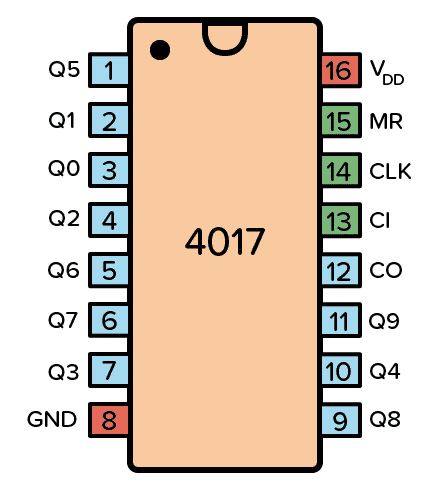
Pin Overview
| Pin Name | Pin # | Type | Description |
|---|---|---|---|
| VDD | 16 | Power | Supply Voltage (+3 to +15V) |
| GND | 8 | Power | Ground (0V) |
| Q0-Q9 | 1-7 and 9-11 | Output | Qx is high when the counter is x |
| CO | 12 | Output | Carry Out. Goes high after ten clock pulses |
| CI | 13 | Input | Clock Inhibit. Ignores clock inputs |
| CLK | 14 | Input | Clock Input. Increases the counter with one |
| MR | 15 | Input | Resets the counter to 0 |
What is a Decade Counter?
A decade counter counts to 10. You can remember it by thinking of a decade in years, which is ten years.
It’s very common that a counter will give you the output in binary form. But the output from the decade counter in the CD4017 is decoded, meaning that it will set one of the output pins (Q0 to Q9) high corresponding to the counter value. Ex: If Q3 is high, the counter value is 3.
The easiest way to create a decade counter is by connecting 10 D flip-flops in series to create a shift register. Then you connect the output of the last flip-flop back into the input of the first. And you connect the reset signal so that it sets the first flip-flop to one and the rest to zero on reset.
This is also known as a ring counter. Below you can see an example of a 4-bit ring counter:

The counter circuit in the CD4017 however, is not a standard ring counter. Instead, it uses a technique called a Johnson counter that makes it possible to achieve the same with only 5 flip-flops plus some logic gates.
Typical applications for the CD4017 include LED chasers, alarms, frequency dividers, or even a music sequencer.

Get the 555 Timer Cheatsheet
A super helpful reference that makes it easy to design circuits, so that you can build oscillators, timer circuits, and more in no time.
How To Use The CD4017
First of all, you need a power supply voltage of 3 to 15V. Most versions of the chip support up to 18V. But for instance, the HEF4017 recommends only up to 15V.
Connect the VDD pin to the positive terminal and the GND pin to the negative terminal.
The Clock (CLK) pin increases the counter with one every time the pin goes from low to high. And as the count increases, the output pins (Q0-Q9) get high one by one. After the 10th input pulse, the counter resets and starts from 0 again. Change this pin from low to high to increase the counter.
The output pins Q0 to Q9 goes high one by one as the counter increases. Connect each to a resistor and LED if you want to see pins change state.
The Clock Inhibit (CI) pin disables the counter so that any clock pulse on the CLK pin is ignored. Set this pin to low to enable the counter.
The Carry-out (CO) pin goes from low to high when the counter reaches 10 and resets back to 0. It stays high for 5 clock pulses, then goes low again. Connect this pin to the clock input of another decade counter if you want to count higher than 10.
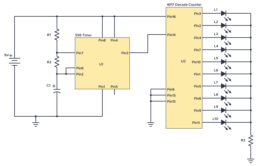
CD4017 Example Circuit – Running LEDs
One of the most popular hobbyist projects to build with this chip is the running LEDs circuit. It works like this:
A 555 Timer is set up in astable mode, which makes it into an oscillator circuit that creates a clock signal. This clock signal goes into the clock input of the IC 4017. Every time the clock input goes high, the counter in the 4017 increases, which makes the next output HIGH. LEDs are connected to each of the outputs and therefore appear to be “running” along a line.
Here’s the circuit diagram:
Component List
| Part | Value | Note |
|---|---|---|
| R1, R2, R3 | 10 kΩ | Three standard resistors |
| C1 | 4.7 μF | Polarized capacitor |
| L1 to L10 | LED | Standard light-emitting diode |
| U1 | NE555 | 555 Timer IC |
| U2 | CD4017B | 4017 Decade Counter |
Note: Some versions of the 555 IC require a 0.01µF capacitor between pin 5 and ground/minus.
The LEDs blink in sequence from the first to last and then starts from the first again. You can use this technique, for example, to create blinking Christmas lights.
After reaching Q9, the 4017 will restart the count and restart from Q0. If you want to limit the number of LEDs, all you have to do is connect the corresponding next output bit to the MR pin.
For example, if you have only 5 LEDs, connect the Q6 to the MR pin. When the count reaches the 6th bit, it sets the MR pin and resets the operation.
With some small modifications to the circuit above, you can build the knight rider LED bar:
How To Set the “Running” Speed
The number of times the output from the 555 Timer goes HIGH per second is the frequency and is given in Hertz (Hz). For example, 10 Hz means ten times per second. And that means the LED moves 10 positions per second.
The resistors R1 and R2, and the capacitor C1 decide the frequency according to this formula:
Frequency: 1.44 / ((R1 + R2 + R2) * C1)
Note: R1 should never be less than 1 kΩ as it might damage the chip when Pin 7 (Discharge) is connected to ground.
If you want to try different values, you can use this 555 Timer calculator to help you.
Alternatives and Equivalents for CD4017
You likely find the 4017 IC marked as CD4017, NTE4017, MC14017, HCF4017, TC4017, or HEF4017. Usually with a few extra characters at the end (Ex: CD4017BE).
This has to do with the manufacturer of the chip and the technology used. But the functionality and the pins are the same.
If your local electronics store doesn’t have any of these chips, check out my list of online stores for other places to buy from.
The CD4017 is a very common IC, so you should be able to find it in one of the online stores. But as an alternative, it’s possible to use a BCD counter such as the CD4510. Then connect the output of it into a CD4028.
4017 Datasheet
Download the PDF datasheet for the IC 4017 here:
CD4017BE (Texas Instruments)
HEF4017B (Nexperia)

Build Something Useful This Evening
This gadget lets you use any IR remote-control to control your lamp, garden lights, heater oven, garage door, or anything else.