Christmas is coming up, so why not set aside an hour or two to build this blinking Christmas lights circuit?
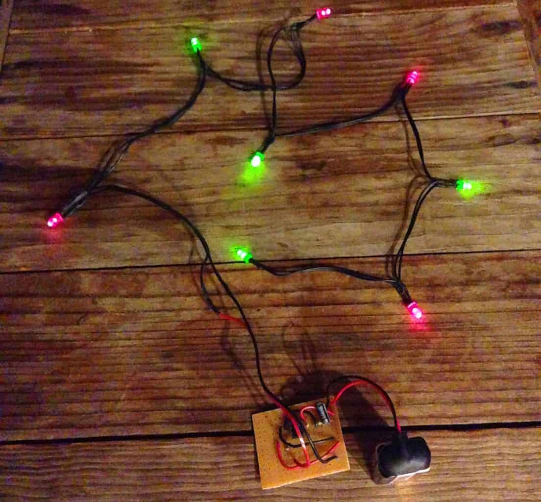
This circuit is easy to build and it’s something you can put to use right away. I built this and hung it in the window, something my girlfriend loved!
The blinking part of the circuit is made up of only 4 components. Then you’ll add as many lights as you want.
How To Blink Lights
There are several ways to blink lights. I’ve previously written about how to blink a light using transistors or a relay. Another method is to use a microcontroller.
But, I think one of the easiest ways, at least in terms of the “easiness” of building the circuit, is using a 555 timer.
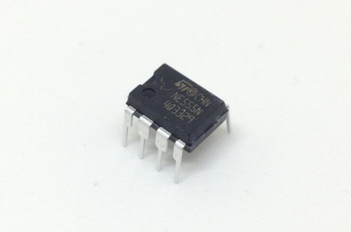
The 555 timer is a chip that you can use for creating a signal that turns on and off repeatedly. That’s exactly what you need for blinking Christmas lights!
Just connect this signal to some LEDs and a resistor to control the LED currents.
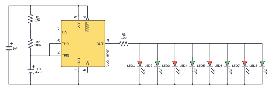
Blinking Christmas Light Circuit Diagram
In this circuit, you’ll only need 4 components + the LEDs and the resistor.

Build Something Practical This Evening
Download this tutorial that shows you step by step how to build an old-school USB charger for your mobile.
To get the blinking effect, you need to set the 555 Timer in astable mode. Then its output will change between 9V and 0V repeatedly.
Here’s the full circuit (see further down for the parts list and explanation):
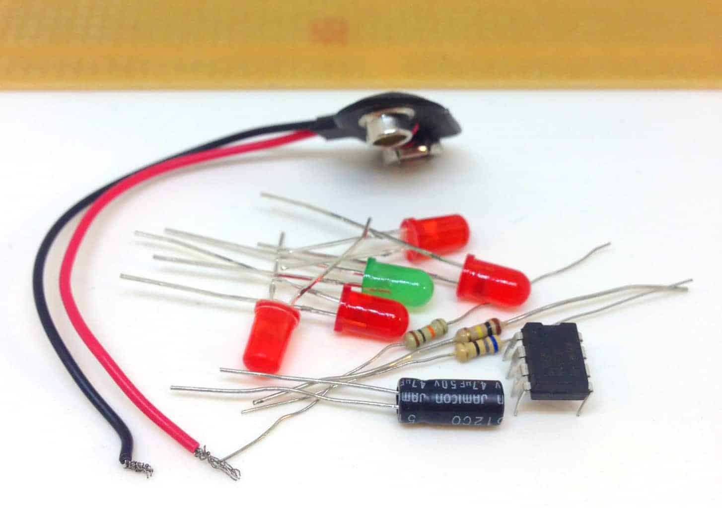
Parts List
| Part | Value | Description |
|---|---|---|
| U1 | LM555 | 555 timer |
| C1 | 4.7 µF (10V and upwards) | Capacitor |
| R1 | 10k Ohm | Resistor |
| R2 | 100k Ohm | Resistor |
| R3 | 100 Ohm | Resistor |
| L1 – L8 | Standard Output LED | Light-Emitting Diode |
Setting The Blinking Speed
Two resistors and a capacitor is all you need to set the blinking speed. You can calculate the number of “blinks” per second with this formula:

But, an even easier way is to use this calculator. Then you can try with whatever values you have at home and see what result you can expect.
With the values I’ve chosen, you should get about 1.5 blinks per second. And the time the LEDs are on should be about the same as the time they are off.
Setting The LED Brightness
When you light up an LED you should always use a resistor, so that you can control how much current that goes through it.
10-15 mA is usually a good current amount for standard output LEDs. In this circuit, you have eight of these in parallel. That means you need 80-120 mA in total for the eight LEDs. This also means you want this much current to flow through the resistor. The current going through the resistor will be the amount of current that will be shared among the LEDs.
If this reasoning does not make sense to you, I recommend you read my article What You Need to Know About Current, Voltage and Resistance.
The LEDs I used had a forward voltage of about 2V. So, a 100 Ohm resistor is a good match. You can learn how to calculate the correct resistor value for any LED in my article about current limiting resistors.
If you’re thinking about adding more LEDs, keep in mind that the 555 timer only supports around 200 mA of current. For example 20 LEDs with 10 mA.
Soldering the LEDs
I used a cable from some old headphones to connect the LEDs. Then I used heat shrink tube to cover up the solder joints.
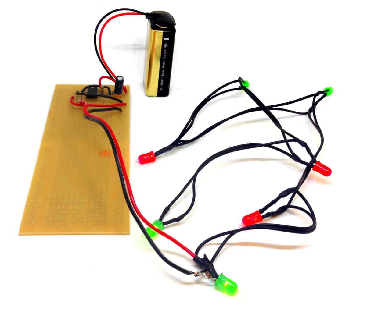
My Blinking Christmas Lights
If you built this circuit, let me know in the comment field below. Also, for any questions about modifications or anything, use the comment field below.
More Circuits & Projects Tutorials

10 Simple Steps to Learn Electronics
Electronics is easy when you know what to focus on and what to ignore. Learn what "the basics" really is and how to learn it fast.
Hi Oyvind, thanks for this tutorial. I love the way you explaned things, practically, from the basics, with tools very helpfull (pictures, web sites…, circuit…). Have a nice – blinking – day !
I’m glad you liked it!
Best,
Oyvind
Dear Sir ,, can you please write which power resistor should be chosed for this circuit. You have mentioned just resistance but not power. Does it matters?? Plz help me.
Thank you Sir.
The LED current limiting resistor was determined assuming that all 8 LEDs are connected. If a wire breaks i.e. all 8 are not connected you could destroy those lit. My apologies if I missed this caution.
That being said I admire your efforts to educate! Keep up the good work!
Thanks for your comment!
Oyvind
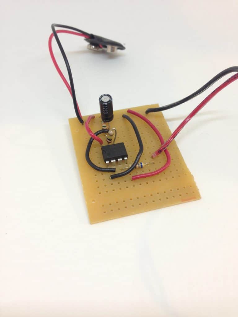
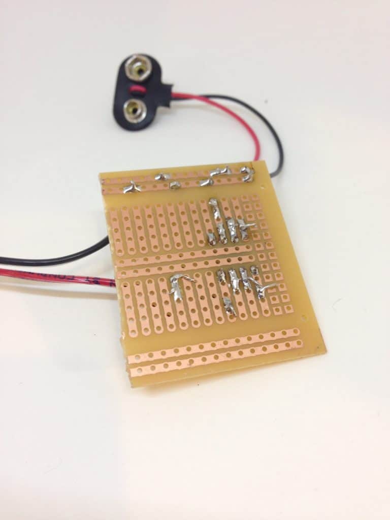
Do you have a better picture of the breadboard so I can see exactly where all of the components go?
This is actually a strip board and not a breadboard. So I’ve soldered the components onto the board (which makes the project more permanent).
I’ve replied to your email with an image, but not sure if it helps…
Best,
Oyvind
Could I also see the image?
I just uploaded them to this article, below the parts list.
It’s so nice I like it. Thank you
Great to hear =)
Oyvind
pls my is not blinking I need ur help
Hi,
Some common errors are:
-connected the IC the wrong way, or not counting the pin numbers correctly
-connected the LEDs the wrong way
-using the wrong component values
Can you make it work with one LED?
Good article for beginners, thank you!
But what about values used in the formula for resistor and capacitor? Were they in kOhms or Ohms and mF or nF? I’ve used online calc you provided – it show absolutely different value.
Hey,
You can see the values in the parts list. kOhms for R1 and R2. µF (microfarad) for the capacitor. It gives you a frequency of 1.462. I just tried the caclulator and got this value.
Maybe you used milli instead of micro for the capacitor?
Best,
Oyvind
Hi.
Using “http://www.ohmslawcalculator.com/555-astable-calculator” i also got 1.462Hz. But i was using formula you posted “=(1.44)/((10+100*2)*4.7)” and IT gives me “0.001458967” as a result.
Please advise.
Thank you.
Oh, yes. You need to use the following:
10k = 10000
100k = 100000
4.7µF = 0.0000047
Best,
Oyvind
Oh…
I’ve got it! Thank you very much! That is much handy than online calculator – formula is always with you :)
I have got it thank you very much and happy christmas
Merry Christmas!
Oyvind
Hi,
I’m still new to this and I was wondering how do you determine the resistor values and capacitor value? The LEDs I am using for this have a forward voltage of 3V and I’m still not sure how many LEDs I am going to use. Is there a formula to find the values?
Thank you.
Hey Cinthia,
For values that set the blinking speed, check the “Setting The Blinking Speed” section in this article.
R3 sets the current for the LEDs.
Let’s say you want three LEDs. Each LED needs current. How much depends on your LED, but 10mA is normal, so let’s go with this.
3 LEDs with 10 mA is 30 mA.
You need 30 mA through the resistor R3.
You get 9V out from the 555 Timer. 3V of those 9V will drop over your LEDs. That means you have 6V left to drop over the resistor R3.
Ohm’s law says R = V/I
That’s 6V / 0.03A = 200
So you need a resistor of 200 Ohms.
Learn more about this calculation here:
https://www.build-electronic-circuits.com/current-limiting-resistor/
Best,
Oyvind
Thank you! I appreciate all the help I can get! :)
Dear Oyvind,
I have made the Christmas lights whitout problems and learned from it.
I really like your tutorials and clear explanarion.
Thank you so much.
Happy Christmas to you and all the readers.
Yvonne
Hey Yvonne,
That makes me very happy to hear!
Merry Christmas!
Oyvind
hi oyvnd smashing circuit i replaced the nine volt battery with a phone charger it works great and i spread the leds further apart and built them into a christmas wreath for on my front every one is asking me where i bought it from great idear
That’s really cool! Good job
Best,
Oyvind
This content is really helpful to make such a this type of light, because when we buy it, so its costly and when we make this light by self, it look more beautiful.
LED driving voltage ranges depend upon color. These voltage ranges do not necessarily overlap and probably depend upon the manufacturer as well. So if the voltage on a parallel design is too low for some LEDs the higher voltage ones will not light. If driven at the higher voltage, the lower voltage ones quickly burn out. So, you cannot necessarily drive a color mix with the circuit described. One internet source sells a selection of 5 LED colors. The voltage range for yellow and red is 1.8 to 2.3 volts and the range for blue, green and white ones is 2.8 to 3.3 volts. This circuit will not drive a mix of colors drawn from these two groups.
Great input, thanks!
3 led glowing kar sakthe he kya…?
Good job sir,
let me try it with my students and see how it works
Thanks for the circuit! As one of the earlier posts suggests, the LEDs have to be the same colour (or at least similar forward voltage) to work welll.
Is there a way use the 555 timer and separate the LEDs into two groups so that they’re on alternate cycles? (What I mean is group1=on & group2=off; group1=off & group2=on; and repeatedly cycling in that pattern.)
Thanks!
Yes, that’s possible. Check the following example on how to connected two LEDs that alternate. Then just add more resistors in parallel two both the upper and lower LED:
http://myelectronicshub.blogspot.no/2014/07/rail-road-crossing-flashing-led-using.html
I love your tutorials. Keep it up
Thanks! =)
GREAT ARTICLE
NOW ASSUMING I WANT THE LED S TO BLINK IN A RANDOM ORDER OR OR RISING ORDER CAN I DO IT WITH 555 TIMER AS WELL?
THANKS IN ADVANCE.
For a running LED-effect you can combine the 555 timer with a 4017 counter:
https://electrosome.com/led-chaser-ic-4017-ic-555/
For a seemingly random order, you can connect the LEDs like in the above diagram, just mix up the order.
Best,
Oyvind
Sir. Thanks. Via the blinking formula of d light. Where is the 1.44 coming from ?
I am not sure. I’ve never dissected the formula.
PlS sir. Can i add R4 to IC pin 3. and add another set of the same LED color to cct.
Yes you can. But you can also just change the value of R3 to give you the current that you need for the number of LED you have.
Best,
Oyvind
Quick question. I’m still a bit new to this but how do you know the limit of LEDs you can use? For example, I have 8 LEDs that have 24mA each and I am planning on using a 9V battery. Each has a forward voltage of 3V.
Thank you.
Check the max current that your 555 timer can provide. You’ll find it in the datasheet. For example this one can provide up to 200 mA:
http://www.ti.com/lit/ds/symlink/lm555.pdf
So if you want your LEDs to be at maximum brightness, 24mA, you can have 200 divided by 24 LEDs. That’s 8 LEDs. If you run less current through the LEDs, for example only 12mA, you can have 16.
Oyvind
Thank you for your reply. Really appreciate the help :)
Hi.. I have a question.. I bought about 50 green single leds.. Now.. I want to. Connect them to a solar panel.. Kind of like the solar lights… (bare with me on the lingo, I know nothing) I want each led light to be connect to a single wire coming from solar thing.. So. I will have 50 green led lights on the end of 50 separate wires. All ranging from 1ft. To 20ft…but… I want a blinking sequennce to be slow and dimming where each light dims on and off slowly. And almost at differant times.. Please help me.. Thank you in advance.
como faço pra colocar 97 lampadas de resistores piscando?
com uma frequencia de forte pra fraco e que achei e queria aproveita-lo
I have a question to ask regarding the paragraph 4 in the subtopic 4 “Setting the LED brightness” and that is how did you end up determining the value of limiting resistor as 68 Ohm. As far as I know that you found it for one LED so the current is around 15mA for 1. So, as R= V/I that is 2V/0.015A gives 133.3 ohms. Can you please explain.? Thank you in Advance.
Hi, the 2V is what drops over the LED. The rest, 7V, drops over the resistor. So you need to use 7V to calculate the current.
7V/68 Ohm = 103 mA
There are 8 LEDs, so each led will get about 13 mA.
How to make LEDs on and off sequentially, like representing flow of current for demo purpose
Great explanations! Have you ever used the old-fashioned (non-LED) Christmas lights? I was recently given many strands, and this would be a terrific project. :)
I haven’t. But those bulbs use a lot more current, so you’d probably need to use a transistor that can handle enough current in between the 555 and the lights.
How can I create a pattern of the lights blinking differently from each other with a speed control? Thanks!
Hi..
I try adding the Green Led together with Red led but it seems the green brightness lever too low
Could you advice how to add green led with the circuit thanks you
Thanks
1. How did you calculate the resistors required? Tried online but no luck.
2. If the power is changed to 6V, which of the components would change? Same question for 12V?
3. I want to install 20 of either 3mm or 5mm LED.
The project is for lights on an Xmas tree cut out on the scroll saw. Holes will be drilled for the LED’s.
Here’s a link to how to calculate the resistor value for one LED: https://www.build-electronic-circuits.com/current-limiting-resistor/
For multiple LED, just multiply the current. Ex 10 LEDs with 10mA each, you need 100mA through the resistor.
Thanks very much, appreciated.