The 74×14 (ex 74HC14) is a common logic IC with six Schmitt-trigger inverters. I love this chip because you can do a lot of cool stuff with it (oscillators, sound, blinking, etc).
In this guide, I will show you everything you need to know about this chip so that you’ll be prepared to build your own projects based on this chip.

What does the 74HC14 / 74LS14 do?
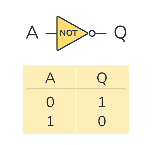
The 74×14 gives you six NOT gates that you can use individually. A NOT gate (or inverter) is a logic gate that outputs the opposite of the input. In the truth table below, you can see what the output will be for any given input:

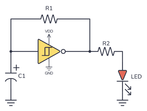
The gates have Schmitt trigger inputs, which means that the threshold voltage for going from a HIGH to a LOW input is different from the threshold for going from LOW to HIGH. Because of this, it’s possible to design an oscillator by just adding a resistor and a capacitor to the gate.
You can see an example of this in the Circuit Example section further down.
How To Use This Chip
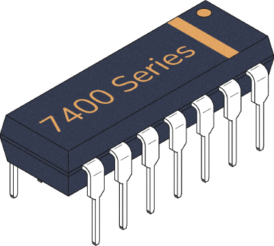
The 74HC14 comes in a 14-pin package, and you need to connect it to power before you can use it. Most 7400 ICs support a VCC voltage of 5V. One of the differences between the HC and LS chips is that the 74HC14 supports 2V to 6V, while the 74LS14 only supports 5V.
There’s also a 74C14 version that supports up to 15V (and 15 mA of current), but it’s not that easy to find anymore.
To use any of the six Schmitt-trigger inverters inside, just power on the chip by connecting the VCC pin to 5V and the GND pin to 0V (or minus).

10 Simple Steps to Learn Electronics
Electronics is easy when you know what to focus on and what to ignore. Learn what "the basics" really is and how to learn it fast.

74×14 Pinout
The 74×14 has 14 pins and contains six Schmitt-trigger NOT-gates laid out as shown in the pinout diagram below:

| Pin # | Type | Description |
|---|---|---|
| 1 | Input | Input to the first NOT gate. |
| 2 | Output | Output from the first NOT gate. |
| 3 | Input | Input to the second NOT gate. |
| 4 | Output | Output from the second NOT gate. |
| 5 | Input | Input to the third NOT gate. |
| 6 | Output | Output from the third NOT gate. |
| 7 | Power | Connect to ground (GND). |
| 8 | Output | Output from the fourth NOT gate. |
| 9 | Input | Input to the fourth NOT gate. |
| 10 | Output | Output from the fifth NOT gate. |
| 11 | Input | Input to the fifth NOT gate. |
| 12 | Output | Output from the sixth NOT gate. |
| 13 | Input | Input to the sixth NOT gate. |
| 14 | Power | Positive power supply (VCC). Connect to +5V power. |
74HC14 Example Circuit – Blinking an LED
In this example, you’ll build an oscillator that blinks an LED at a rate of about 1 time per second. This is one of the simplest oscillators to build, and you can easily use it for other stuff like creating sound.
You’ll need the following components to build this circuit:
- 2-6V Voltage Source
- Schmitt Trigger Inverter (74HC14)
- Capacitor of 100 µF (C1)
- 2 x Resistor of 10 kΩ (R1 and R2)
- A Light-Emitting Diode (LED)
I’ve written a guide on how to build this circuit over at this page, if you want step-by-step instructions on how to build this.
Alternatives and Equivalents for 74HC14 / 74LS14
There are several versions of the 74×14 chip out there. They all do the same thing but have different specifications. This could mean differences in the voltages they support or the maximum current they can provide.
Here’s a list of the most common versions of this chip:
- 74C14 (CMOS, similar to the 4000-series)
- 74HC14 (High-speed CMOS)
- 74HCT14 (High-speed CMOS, TTL compatible)
- 74LS14 (High-speed TTL)
- 74LVC14 (Low Voltage TTL)
- 74AC14 (Advanced CMOS)
- 74ALS14 (Advanced Low-Power Schottky TTL)
- 74F14 (Very High Speed)
Note that some manufacturers also add a prefix, such as the SN74HC14 and SN74LS14 by Texas Instruments. There is also a 54 series which you can use in the same way.
Can’t find the 74×14 anywhere? Then try one of the following IC alternatives:
- 74×04 – Hex NOT gate
- 74×05 – Hex NOT gate (with open-collector outputs).
- CD40106 – Hex Schmitt-trigger NOT gate
If you can’t find the 74×14 IC (Integrated Circuit) in your nearby electronics store, no need to worry! You can probably locate it in one of the online stores listed on this page. These stores offer various components and tools for all your electronics projects.
Datasheets for the 74LS14 and 74HC14 chips
- SN74HC14 (Texas Instruments)
- SN74LS14 (Texas Instruments)
- MM74C14 (Fairchild)
- 74HC14 (Futurlec)
- 74LS14 (Futurlec)
- 74HC14 (Diodes Inc)
- 74HC14 (Nexperia)

Build Something Useful This Evening
This gadget lets you use any IR remote-control to control your lamp, garden lights, heater oven, garage door, or anything else.


In the table above showing the input and output of pins 8-13 are labeled incorrectly compared to what it shows in the diagram above
Thanks a lot, Ron! It was an error with my pinout-generation script. Updated it now.
I have a hex schmitt trigger inverter that is supplied 5V VCC but the high signal is 5V and the low signal is 1.5V. The indicator diodes detect the switch but in the inverter whether input is high or low the output is always .19V. I’ve tried several chips and even started replacing chips in support circuits and still can’t find the issue. What determines the output of the trigger? Is it based solely on the input voltage? Why does a low or high on the input do nothing on the output for just pins 3-4 and 5-6?
Hi Doug,
From the datasheet of the 74LS14 chip, it says that the input must be lower that 0.8V typically (0.5 in some cases) to register as a LOW input. So if your input is always 1.5V or higher, the output will always be LOW.
You’ll find this value on page 5 in the datasheet (VT-):
https://www.ti.com/lit/ds/symlink/sn74ls14.pdf