• Skip to primary navigation
  • Skip to main content
  • Skip to primary sidebar
  • Skip to footer
Build Electronic Circuits

Build Electronic Circuits

Electronics explained in a simple way

  • Start Learning
    • Basic Electronics
    • Digital Electronics
    • Circuits
    • Practical Skills
      • Printed Circuit Boards
    • Microcontrollers
      • Arduino
    • Maker Lifestyle
      • Podcast
    • Academy
  • About Me
  • Blog
  • Academy
  • Contact
You are here: Home / Circuits / Build Instructions: The Blinking Light Circuit

Build Instructions: The Blinking Light Circuit

May 24, 2019 By Øyvind Nydal Dahl 82 Comments

Do you want to build a circuit that blinks a light? This inverter-based circuit is simple, and it’s small enough to fit on a breadboard.

The circuit uses standard basic electronic components and you can build it even if you have never built anything before. Check out the full build instructions in the video below:


Scroll down to find the complete circuit diagram, component list, and step-by-step instructions (in text-form) on how to build this circuit.
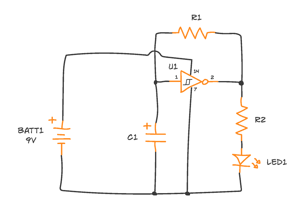
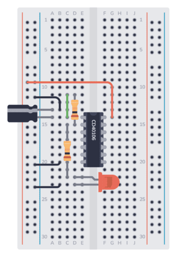
This circuit is from my Free Email Course on how to make a light blink. Do you know anyone else who would love to learn electronics? Please share that link with them.

The Circuit Diagram

In the lessons, you learned that you needed an inverter for this circuit. But there’s one important point if you want to build this:

You need to use a Schmitt-triggered inverter. It’s an inverter where the voltage at which it switches from LOW to HIGH is higher than the voltage for switching from HIGH to LOW.

You’ll find the complete circuit diagram below.

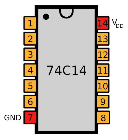
The numbers next to each pin in the diagram represent the pin number on the integrated circuit. Click here for the pinout of the Hex Schmitt Trigger Inverter IC.

The Components You Need

PartValueNote
–BreadboardBreadboard
–2 x Jumper WiresAny stiff wire (22-23 AWG)
–9V Battery clip To connect battery to board
BATT19V BatteryTo power the circuit
U174C14 or CD40106Hex Schmitt Trigger Inverter
C1100μFPolarized capacitor
R110 kΩAny resistor type
R210 kΩAny resistor type
LED1RedStandard LED (low power)

These are pretty standard components that you can get from most places that sell parts for building electronics. I’ve created a page with a list of where to buy electronic components here. They’re also included in the Ohmify Beginner’s kit (except the battery).

Build The Circuit Step-by-Step

When you have the components in hand, you’re ready to build the circuit.

Not sure how the breadboard works? Then you might want to read How To Use a Breadboard first.

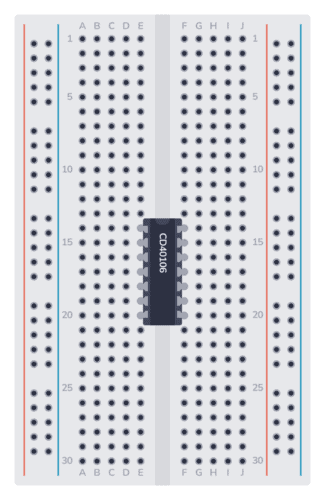
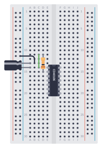
Step 1: Place the Integrated Circuit (U1)

The chip place on the breadboard

Start with U1, the Hex Schmitt Trigger Inverter IC. Place it across the gap in the middle, with pin 1 in the upper left corner.

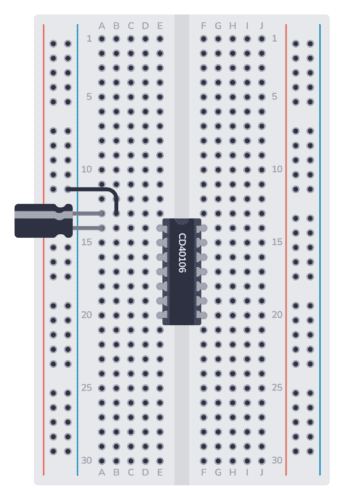
Step 2: Place the Capacitor (C1)

Next, place the capacitor C1. First, find the negative pin. It should be marked with minus or zero. Often the negative pin is shorter than the positive pin.

Connect the negative pin in the negative supply column. And connect the positive pin to the same row as Pin 1 of the IC.

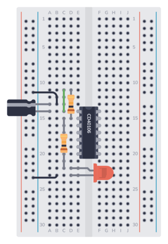
Step 3: Place the Resistor (R1)

The resistor R1 should go from the input (Pin 1) to the output (Pin 2). Bend the legs of the resistor so that you can connect it from the row of Pin 1 to the row of Pin 2.

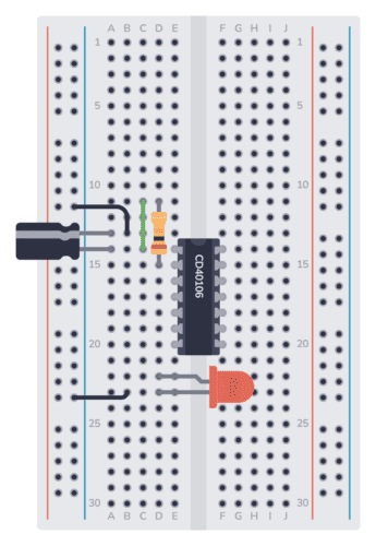
Step 4: Place the LED (LED1)

Next, connect the LED. The negative leg of the LED is the shortest one. Connect it to the negative supply column. Connect the longer leg to an empty row.

Step 5: Place the Resistor (R2)

The resistor R2 connects the output (Pin 2) to the LED. Place one leg of the resistor into the row of Pin 2. Place the other leg on the same row as the long leg of the LED.

Step 6: Connect GND to Minus

The GND (Pin 7) of the IC must be connected to ground. In this circuit, ground is the minus of the battery. Connect one end of a jumper wire to the same row as Pin 7. Connect the other end to the negative supply column.

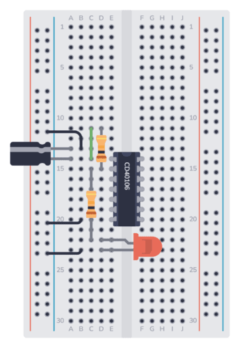
Step 7: Connect VDD to Plus

The VDD (Pin 14) of the IC must be connected to the positive supply. Connect one end of a jumper wire to the positive supply column. Connect the other end to the same row as Pin 14.

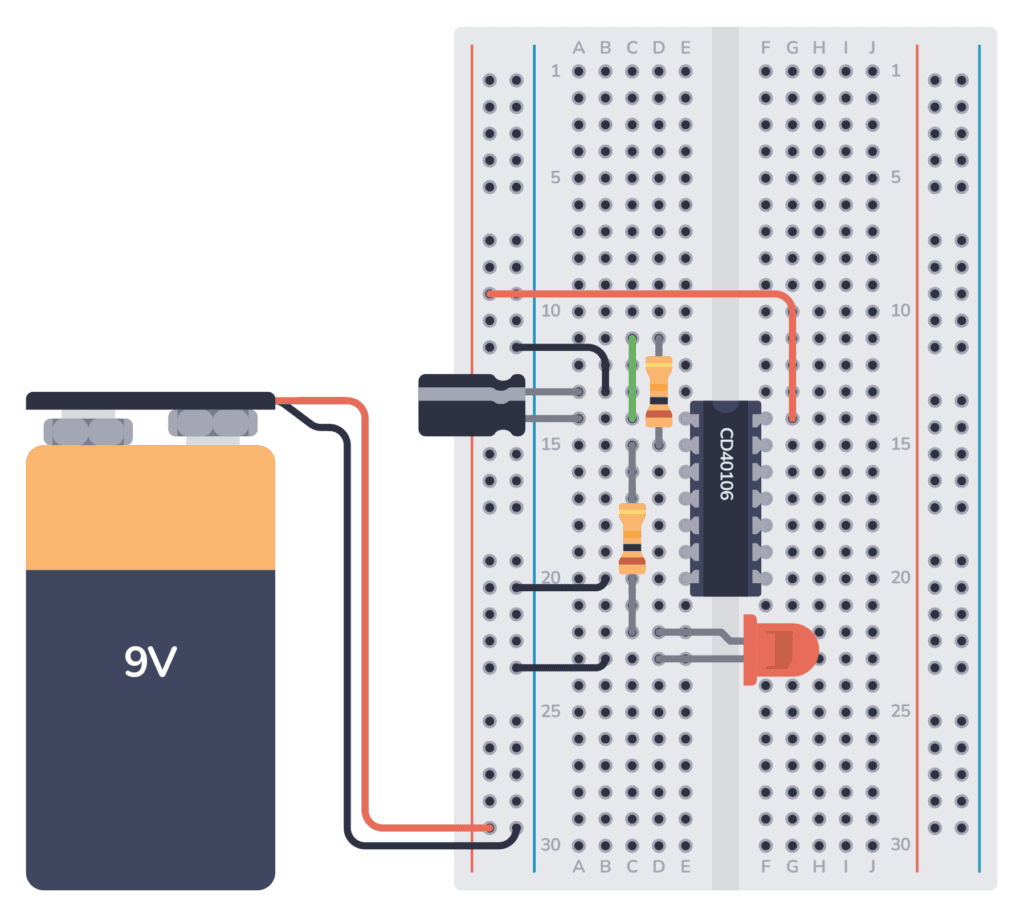
Step 8: Connect the Battery

Finally, connect the red wire from the battery to the positive supply column. And connect the black wire to the negative supply column.

Your LED should start to blink.

Questions?

Did you build it? How did it go?

Let me know in the comments below.

Filed Under: Circuits

Reader Interactions

Comments


  1. Ed says

    May 27, 2019

    Hi
    I’m looking to build a Star Trek TNG TRICORDER light and sounds,
    But I’m not sure how to do it. Any information you could share, would be much appreciated. Or where I could find that information. They used to sell them on eBay, but I cannot find any.

    Reply

    • bruce hull says

      July 22, 2019

      still struggling with the blinking light. My energy source is a solar light for area lighting with a 3.7 volt Li-ion 800 mAh rechargeable battery. it’s currently reading 2.11 volts. I’m not sure on the pin outs of the inverter. Actually I would love a pin out on the schematic.

      Reply

      • Phil Karras, KE3FL says

        July 14, 2020

        7404 is the original TTL chip, look it up by searching on 7404 datasheet, in fact you can search on anything that way, 74c04 data sheet.

        But pin 1 = input to first inverter, pin 2 = output of 1st inverter, the 74C04/7404, etc is a six inverter IC pin 7 = return/ground, pin 14 = Positive Voltage power source. For TTL 7404 that 4.75 – 5.25 volts, for 74C04 we know it’s at least up to 9V.
        Inverter input pins
        1
        3
        5
        —-7 = Gnd
        8
        10
        12
        —-14 = + power input

        Inverter output pins
        2
        4
        6
        —-7 = Gnd
        9
        11
        13
        —-14 = + power input

        Reply

        • Ali Yoosuf says

          September 16, 2020

          it is very interested thank you so much.

          Reply

        • Sirmseen says

          January 10, 2022

          How did know this?

          Reply

  2. Bruce says

    May 30, 2019

    Great information. I’m looking to have a LED blink but I want the LED to slowly light and then slowly go off. In a two second cycle loop. Any suggestions?

    Reply

    • ArpitaS says

      September 25, 2019

      Maybe use a adruino board?

      Reply

    • Ajaz Amin says

      November 5, 2019

      U can use a dimmer led instead but that will blink rapidly and slowly light off

      Reply

    • Sheperd Musira says

      August 11, 2021

      It is quite good and easy to follow .I do not know if the mismatch happens

      Reply

  3. AlbeOutlaw176 says

    June 2, 2019

    Yes I have a Comment why don’t you build it step by step show how to build it not just to show it light up ?

    Reply

    • admin says

      October 16, 2019

      I just updated the article with step by step instructions. Hope you’ll find it useful!

      Reply

  4. bruce hull says

    June 19, 2019

    OK, list the parts and where I can get them. I would have loved this sixty years ago but right now I want to finish my prioject AND I do see future projects that wil required me to dig a bit deeper.

    Reply

    • admin says

      June 20, 2019

      Hi Bruce,

      Here’s a page with several options on where to buy the components from:
      https://www.build-electronic-circuits.com/buy-electronic-components/

      Best,
      Oyvind

      Reply

  5. Niladri Patra says

    June 26, 2019

    Hi,
    I want to make 3v LED Flash light with LDR.
    This type of light is using fishing purpose in sea.
    Regards
    Niladri

    Reply

  6. Ben says

    July 12, 2019

    I am still unsure about how the voltage interacts with the inverter. If I track the current, it leaves the positive pole of the 9V and travels directly to the inverter (at the input labelled 14). I assumed that this was the power supply to the inverter and would be constant. And that this voltage would exit through the output labelled ‘7’ and return to the battery. Is this an activating voltage that would then cause the inverter (with no initial voltage at the input labelled ‘1’) to output a voltage at ‘2’, which would loop around and cause the inverter to switch, initiating the on/off loop? Sorry if this is confusing…

    Reply

    • admin says

      July 15, 2019

      The pins 14 and 7 are for powering the inverter. When the output is HIGH, it’s from here the output gets its voltage and current, yes.

      Reply

  7. bruce hull says

    July 22, 2019

    OK…update. I triple checked the schematic and used a couple of combinations. First I used a 9 Volt battery with the solar light and later on LED and in both setups I got a strong resulting illumination. I then used the solar panel with the 2.1 volts with both LET setups and got a average illumination result. The appears to be a slight flickering of the lights but it is very low and fast. Hard to detect at first. What is next?

    Bruce

    Reply

    • admin says

      July 24, 2019

      Check out the datasheet for the chip:
      https://www.mouser.com/ds/2/308/mm74c14-1193355.pdf

      From there you can see that the chip needs at least 3V. So 2.1 will probably give unreliable results.

      Reply

  8. bruce hull says

    July 25, 2019

    I appreciate your response and that makes sense regarding the voltage level but I had the same results when I substituted a nine volt battery as the power source. My power source is a yard light that comes on at night and goes off during day light hours. The light works fine in the constantly on position but I can’t get the slow on and off that I need for my project. Any suggestions as to possible substitution?

    Reply

    • admin says

      July 29, 2019

      Are you saying that your circuit is not blinking when you use a 9V battery? One potential error is that the LED draws too much current. Try replacing the resistor in series with the LED with 2000 ohms.

      If it’s still not working, measure the battery voltage when it’s connected to the circuit. If it’s less than 9V, you might have a battery that is almost dead. Try replacing with a new one.

      Reply

  9. bruce hull says

    July 30, 2019

    new 9 v battery. I really need to get this to work with the solar panel so the batteries will recharge. the rechargeable batteries are 3.7 V. back to the drawing board.

    Reply

  10. bruce hull says

    July 30, 2019

    So basically for this project to work as designed I need to use the solar panel (Wal Mart outdoor light) Which is powered by a 3.7 Li-ion battery. There’s lots of sunlight in south Mississippi. Will that work with your design?

    Reply

    • admin says

      August 14, 2019

      The circuit in this article should work fine with voltages above 3V. But you might need to adjust the resistor for the LED.

      Reply

  11. bruce hull says

    August 23, 2019

    It Works but it is blinking a little too fast. What rate resistor do I need to use instead of the 470?

    Reply

    • admin says

      August 23, 2019

      It’s the 10k resistor or the capacitor you need to change to change the speed. You can for example try doubling the resistor value to 20k.

      The 470 resistor sets the brightness of the LED.

      Reply

  12. Garry Cronin says

    August 23, 2019

    hi Oyvind,

    I notice in your “Basic Electronic Components” ebook you provide a schematic for a Blinking LED using a 555 Timer IC. Can you compare and contrast the pro’s and con’s of building it that way, compared to the way you show here in this article please?

    thanks
    – Garry

    Reply

    • admin says

      August 30, 2019

      The inverter uses less components. But other than that, for blinking an LED they’re pretty much the same.

      Reply

  13. Robert B Moore says

    September 20, 2019

    A step by step assembly video or series of drawings would certainly help this old person. I find it difficult to tell where to hook the components up on the breadboard.

    FYI: I hope to use a modified version of this circuit to drive five LEDs on the rear pair of arms on my first quadcopter.

    Reply

    • admin says

      October 16, 2019

      Hey Robert, I just updated the article with step by step instructions. Hope you’ll find it useful!

      Reply

  14. ArpitaS says

    September 25, 2019

    The video is not there for me.

    Reply

    • admin says

      October 16, 2019

      It’s a youtube video. And it’s there. Maybe you’re on a network that blocks youtube?

      Reply

  15. Openplanet says

    November 7, 2019

    With all due respect, nowhere do you explain the THEORY OF OPERATION of this circuit! Without this, how can a novice possibly understand HOW and WHY it works?!

    I’m a long time electronics hobbyist, so it’s no problem for me. But I’m quite amazed at the absence of an EXPLANATION in what is supposed to be a LEARNING thing.

    Reply

    • admin says

      November 7, 2019

      This is how to build it. The lessons on how it works can be found here: https://www.build-electronic-circuits.com/free-email-course/

      Reply

  16. Mary Patience says

    November 11, 2019

    Would the LED still blink if I eliminated the inverter and worked with only the battery, capacitor and resistors?

    Reply

    • admin says

      November 13, 2019

      No. The inverter is the key to the blinking.

      Reply

  17. Robert Barton says

    November 13, 2019

    I don’t have a cd40106 or a 74c14. I do have a 74ls14 but even with a new battery the led just lights for a moment and then goes out. If I remove and reconnect the battery the light lights for a second and then goes out.
    Is it possible the LS version of the 74 14 is not compatible?
    thanks.

    Reply

    • admin says

      November 13, 2019

      The 74LS14 will only work with a 5V power supply, not 9V. If you switch to a 5V power supply instead of the 9V battery it should work. You might need to reduce the resistor value for the LED a bit.

      Reply

  18. John says

    November 19, 2019

    My light came on but did not blink. Only after I put in a different converter of the same type did it work. Maybe a faulty component? How robust are they? I had to squash the legs to get the inverter onto the breadboard. Took me a bit time to get it to work but it did eventually !

    Reply

  19. admin says

    November 20, 2019

    They are pretty robust. But you can break them if you connect to a higher Vcc voltage than they are rated for. Ex the 74LS14 only works with 5V, while the 74C14 works with up to 15V.

    A typical error is connecting the chip upside down.

    Reply

  20. Chuck Lowe says

    February 10, 2020

    It was great to see the light blink. It looked like the capacitor was in parallel so I pulled
    it out of the circuit and the light went steady. I am enjoying your course and look forward to learning as I grow older. I figure electronics will keep my brain healthy. I ran across an old gentleman back in 1960 who had a mantra he lived by; Sinesco Disens ( I grow old learning.) I think he is right.

    Chuck Lowe

    Reply

    • admin says

      February 11, 2020

      That’s great to hear, Chuck! And there’s always more to learn in electronics =)

      Reply

    • Bob Compton says

      December 27, 2020

      Correction: He stays young learning!

      Reply

  21. Beau says

    April 19, 2020

    My first circuit! Eureka, a blinking light. Great lessons. Thanks Øyvind.

    Reply

    • admin says

      April 20, 2020

      Nice! Congrats!

      Reply

  22. Azli says

    May 23, 2020

    Hi there,

    I find your circuit very easy and straightforward. I found another method of slow blinking/blinking led circuit. Using BC 547, 100μF, 555 timer and some resistors.

    My question to you is, could you help me out to design a circuit to fit in 40 LED with a function of slow blinking?

    Reply

  23. Ken M Takemoto says

    June 16, 2020

    Success! I assembled the components per the tutorial, and it worked the first time.
    The battery connector that came with my kit has a barrel type connector on the end, versus red and black wired pins, but that can be worked around. What I’d like to know is how to insert a button switch (4 prong) with a button into the circuit so I can turn it on and off easily. First electronic project I have ever done.

    Reply

    • admin says

      June 22, 2020

      Congratulations!
      To add a button you can move the long red wire that goes to the upper right corner of the chip. Have that red wire go to one side of your switch instead, and connect a wire from the other side of the switch down to the upper right corner where the red wire was connected before.

      Best,
      Oyvind

      Reply

  24. Vip says

    June 26, 2020

    Can you please explain the working

    Reply

    • admin says

      June 29, 2020

      You can learn it through the free email course: https://www.build-electronic-circuits.com/free-email-course/

      Reply

  25. Maybin says

    June 28, 2020

    What does these initials stand for
    GND
    VDD

    Reply

    • admin says

      June 29, 2020

      It’s the negative (GND) and positive (VCC) voltage connections.

      Reply

  26. Sam Vanroy says

    July 9, 2020

    Using a SN74LVC2G14DCKR, powering with a 3.3v supply to mimic dev board vcc, same circuit. Using a 50 Ohm resistor on the led but can’t figure out the R1 and Cap. I’ve tried many but the led keeps blinking too fast. I’m not grasping the logic of how I should alter the values to slow down the cycle.

    Reply

    • admin says

      July 13, 2020

      Hi Sam, the higher values you choose for R1 and the cap, the slower the LED will blink. If you are using 100 µF now, try with 1000µF.

      Reply

  27. Robert VanHeule says

    July 12, 2020

    this is the blinking light circuit I build this. cool and neat to build the circuit

    Reply

  28. Nisar says

    September 4, 2020

    I am unable to get the IC 74C14 from the market. But I did find IC 74HC14N, but LED is not going to ON or blinking

    Reply

    • admin says

      September 7, 2020

      It should work, but note that the 74HC14 only supports a power supply of 2V to 6V. If you connected 9V you might have broken the chip.

      Reply

  29. Teslāfæn says

    October 13, 2020

    I think for teaching beginners about blinking a light, the relay method is better than this.

    The ‘Hex Schmitt Trigger Inverter IC’ is hard to find both online and offline. (I didn’t try offline. )

    Reply

    • admin says

      October 15, 2020

      You’ll find it as 40106 or 74xx14 (where xx can a number of different letters)

      Reply

  30. Lawrence says

    October 13, 2020

    Hi Oyvind, just tried the circuit, I’m using the sn74sl14n, the led just stays on I’m using the 10k on pins 1 and 2 with a 1k from pin 2 to the led, and using 5 volt power supply.

    Reply

    • admin says

      October 15, 2020

      Hi Lawrence. The sn74ls14n only supports up to 0.4mA output current when output is high. Since you are using a 1k resistor for the LED, you would need 2-3mA to turn on the LED.

      The simplest solution to this is to use a 10k resistor instead of the 1k resistor. This will only work if your LED lights up with only around 0.3mA, but many LEDs will work.

      Reply

  31. Stuart says

    December 6, 2020

    I have just built the flashing led using the Schmitz trigger. It works fine but the led is quite dim.

    Reply

    • admin says

      December 7, 2020

      Great! And yes, the LED will be dim because of R2. 10k is quite high for an LED. You can try with 1k – although depending on which schmitt trigger chip you have it might or might not work. If you have 74C14 it will work. If you have cd40106 it might not work.

      The “best” solution is to add a transistor as a switch to turn on and off the LED – then you can have it as bright as you’d like.

      Reply

      • Stuart says

        December 7, 2020

        Thank you

        Reply

  32. Fire69 says

    January 21, 2021

    Hi,

    Tried building the circuit in Tinkercad (I don’t have the inverter yet) but it’s not working.
    Could you maybe have a look at it? I can’t find what I did wrong…
    https://www.tinkercad.com/things/kdtHfpGMp3r-powerful-trug/editel?sharecode=n5-AFg6EjbR35YzR_qdvH61AsksPEz2fXSrFzwzWGyY

    Reply

    • User17 says

      February 1, 2022

      Same question, did you get any solution to that problem?

      Reply

      • admin says

        February 2, 2022

        The link has expired so I can’t see it…

        Reply

  33. Bhushan says

    February 4, 2021

    Thanks sir for making electronics simple..
    I want your help..
    In this circuits I used 555 timer to blink..
    It works…
    Then make alternate blinking with 2 leds.
    Then make dual alternate blinking all works great…
    ..

    So I want make finally to blink four leds with different times..
    I connect capacitor and resistor by calculating time constant one of those led at one transistor and one at the sides of another transistor…

    It doesn’t work…
    What’s wrong…
    Please describe..

    Reply

    • admin says

      May 24, 2021

      Hard to say without seeing the circuit. But one thing to check is if the current you’re pulling for your LEDs is higher than the current the 555 timer can provide.

      Reply

  34. Weaver, Aaron says

    May 24, 2021

    I finished the blinking LED well it was weak and slow. My son took a look and played with the resistors for pulse rate we used 2.7-22K and 680K for light intensity way better . PS HE HAS DEGREE IN ELECTRONIC.

    Reply

    • admin says

      May 24, 2021

      Great! I assume you mean 680 Ω (without the k). The only thing to be aware of is that the CD40106 can only provide around 1-2 mA of current. The lower you go with the resistor for light intensity, the more current you’ll pull out if it.

      Reply

  35. Gray says

    October 24, 2021

    I have been a Ham Radio Operator for many years but have not had much interest in IC Technologies until this. I have always built equipment. This is new learning and a lot of fun. YOU CAN TEACH AN OLD DOG NEW TRICKS!

    Gray

    Reply

  36. Greg Brannon says

    November 8, 2021

    I’m not an expert in circuit design or analysis, and I’m always learning. I received this circuit discussion in the email tutorial that came with signing up to download your KiCAD guide – a helpful starting point. If the email course hadn’t been a product of the guide, I wouldn’t have looked at it.

    After following the tutorial segment I got each day, it occurred to me that my learning has always been discouraged when ‘magic’ was presented and never adequately explained. Yes, the magic inspires me to dig deeper, but understanding IC magic often requires further explanation by an experienced user. For example, finding, reading, and understanding the important parts of an IC data sheet is not a skill we’re born with. Even though I’ve looked at many IC data sheets, I’d still appreciate having an expert walk me through one with the opportunity to ask questions.

    The email tutorial was an intro course to basic components, but including the IC with less explanation than that given for the resistor or the capacitor was discouraging to me. I like how you described the simpler/basic electronic components in everyday terms that most people can understand. It appears your dad was a good teacher, and you were a good student.

    Keep it up!

    Reply

    • admin says

      November 15, 2021

      Hi Greg,
      Thanks for your feedback!

      Reply

    • Gamini Ratnayake says

      December 1, 2021

      Hi Oyvind !.

      Thanks and the circuit is working so nicely.
      Best regards,

      Reply

      • admin says

        December 1, 2021

        Great to hear!

        Reply

  37. Steve says

    February 10, 2022

    It didn’t work at first. I hadn’t seated the inverter all the way. Now it works fine! Thanks for the instruction.

    Reply

  38. Bob McCool says

    February 19, 2022

    First I would like to thank you for this course. I had zero knowledge of electronics coming into it and now I have a base to continue on learning.
    Long story short I have a LED in my boats bathroom that lights up when the holding tank is nearly full. The float in the tank is the switch. My question is can I use all the components listed here on a 12 V system or should I start at the LED and work backwards to find what voltage I need at each point and use appropriate components ?

    Reply

    • admin says

      February 28, 2022

      Hi Bob,

      For this circuit, you need to make sure the inverter chip can handle 12V. You can do that by checking the datasheet of the chip. If you are using 74C14
      or CD40106, both of these chips support 15V or more, so it will work fine with 12V.

      Reply

  39. Harun says

    April 12, 2022

    Mr.Oyvind I have really enjoyed your lessons so far,I have also tried step by step building simple circuit of LED blinking which is very much successful keep up bro.

    Reply

  40. Roge says

    April 22, 2022

    Hello. Is a capacitor like this likely to blow if powered in reversed polarity? I have seen some videos on the web where they go off pretty badly and I don’t want to make the same mistake.

    Reply

    • admin says

      April 26, 2022

      Not if you’re using a small 9V battery. It might get damaged and loose performance or even stop working, but blowing up – not so likely.

      Reply

  41. Richie Devereux says

    June 20, 2022

    HI, I managed to get it working.
    What are the main uses of the Schmitt trigger & where do you suggest going from here regarding circuits that use the IC?

    Reply

Leave a Reply Cancel reply

Your email address will not be published. Required fields are marked *

Primary Sidebar

Search:

Footer

Topics

  • Basic Electronics
  • Digital Electronics
  • Circuits
  • Practical Skills
  • Microcontrollers
  • Maker Lifestyle
  • Newsletter Archive

Social:

  • Facebook
  • Twitter
  • YouTube

Products

  • Electronics Course
  • Other Products

Copyright © 2022 · Ohmify AS · Terms and Conditions · Privacy Policy