fbpx

NOT Gate (Inverter) – Logic Gates Tutorial

NOT gate truth table and symbol

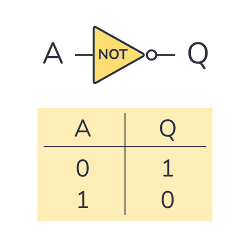
A NOT gate (or inverter) is a logic gate where the output is the opposite of the input. So you can say that the output is NOT the same as the input. It’s often called an inverter since it inverts the input. The schematic symbol for an inverter is like a buffer, just with a

NOR Gate – Logic Gates Tutorial

NOR gate symbol and truth table

A NOR gate is a logic gate where the output goes HIGH (or “1”) only if all its inputs are LOW (or “0”). The schematic symbol for a NOR gate is like the OR gate, just with a circle at the output to indicate that it’s an inverted version of OR. “NOR” stands for NOT-OR

OR Gate – Logic Gates Tutorial

OR gate truth table and symbol

An OR gate is a logic gate where the output goes HIGH (or “1”) if any of its inputs are HIGH. So if A OR B is HIGH, the output Q also becomes HIGH. If A or B is true, then Q is true Truth Table OR gates can have more than two inputs. But

NAND Gate – Logic Gates Tutorial

NAND truth table and symbol

A NAND gate is a logic gate where the output goes LOW (or “0”) only if all its inputs are HIGH (or “1”). The schematic symbol for a NAND gate is like the AND gate, just with a circle at the output to indicate that it’s an inverted version of AND. “NAND” stands for NOT-AND

AND Gate – Logic Gates Tutorial

AND gate truth table and symbol

An AND gate is a logic gate where the output goes HIGH (or “1”) only if all its inputs are HIGH. So if the inputs A AND B are HIGH, the output Q will also be HIGH. If A and B are true, then Q is true Truth Table AND gates can have more than

XOR Gate – Logic Gates Tutorial

XOR gate truth table and symbol

The XOR gate is a logic gate where the output goes HIGH (or “1”) if one – and only one – of its inputs are HIGH. XOR stands for Exclusive-OR. Check out its symbol and truth table below. If A and B are different from each other, then Q is true Truth Table XOR gates

XNOR Gate – Logic Gates Tutorial

XNOR gate truth table and symbol

An XNOR gate is a logic gate where the output goes HIGH (or “1”) only if both its inputs are equal. So if the inputs A and B are both HIGH or both LOW, the output Q will be HIGH. If A and B are the same, then Q is true Truth Table XNOR gates

Logic Gates: Understand The Basics of Digital Electronics

Collection of all the logic gate symbols

Logic gates are the basic building blocks of digital electronics. These are the components that we use for “doing stuff” with the 1s and 0s. You can combine them to create other building blocks like latches, flip-flops, adders, shift registers, and more. The basic logic gates are AND, NAND, OR, NOR, XOR, XNOR, and NOT.