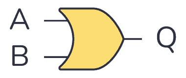
An OR gate is a logic gate where the output goes HIGH (or “1”) if any of its inputs are HIGH. So if A OR B is HIGH, the output Q also becomes HIGH.

The logic or Boolean expression for an OR gate is  which means:
If A or B is true, then Q is true
Truth Table
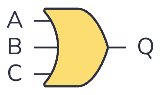
OR gates can have more than two inputs. But no matter how many inputs it has, it will always give out a HIGH or logic “1” if one of its inputs is HIGH.
2-input OR Gate Truth Table
| Input A | Input B | Output Q |
|---|---|---|
| 0 | 0 | 0 |
| 0 | 1 | 1 |
| 1 | 0 | 1 |
| 1 | 1 | 1 |
3-input OR Gate Truth Table
| Input A | Input B | Input C | Output Q |
|---|---|---|---|
| 0 | 0 | 0 | 0 |
| 0 | 0 | 1 | 1 |
| 0 | 1 | 0 | 1 |
| 0 | 1 | 1 | 1 |
| 1 | 0 | 0 | 1 |
| 1 | 0 | 1 | 1 |
| 1 | 1 | 0 | 1 |
| 1 | 1 | 1 | 1 |
IC Alternatives with OR Gates
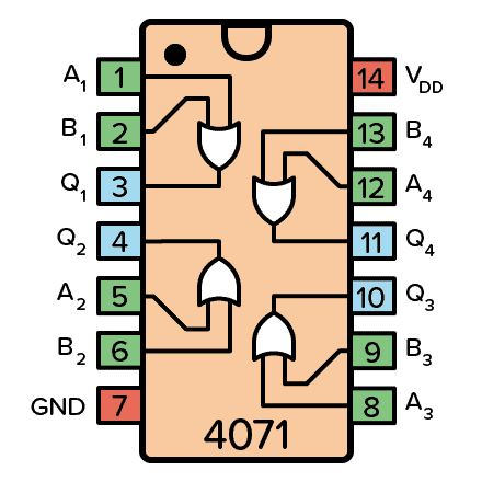
If you want to experiment and build circuits with OR gates, you’ll find them in both the 4000 IC series and the 7400 IC series:
- 4071: Four 2-input OR gates
- 4075: Three 3-input OR gates
- 74HC32: Four 2-input OR gates (HC is the family, can also be LS/HCT/…)
- 74HC4075: Three 3-input OR gates (HC is the family, can also be LS/HCT/…)
These should all be available as hobbyist-friendly through-hole chips. Just make sure you buy the DIP package version.
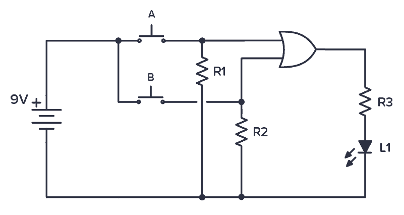
Example Circuit: Testing an OR gate
Below is a simple practical circuit you can build to test how this gate works. A Light-Emitting Diode (LED) turns on when you press either of the buttons A OR B. The circuit demonstrates the basic operation of an OR gate.
More Logic Gates Tutorials

Get Our Basic Electronic Components Guide
Learn how the basic electronic components work so that circuit diagrams will start making sense to you.
