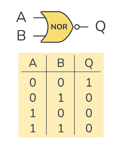
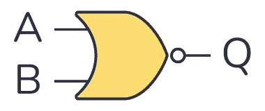
A NOR gate is a logic gate where the output goes HIGH (or “1”) only if all its inputs are LOW (or “0”). The schematic symbol for a NOR gate is like the OR gate, just with a circle at the output to indicate that it’s an inverted version of OR.
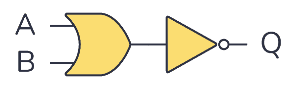
“NOR” stands for NOT-OR because it’s the same as an OR gate with a NOT gate on the output.
The logic or Boolean expression for a NOR gate is  which means that:
If A or B is true, then Q is false
Truth Table
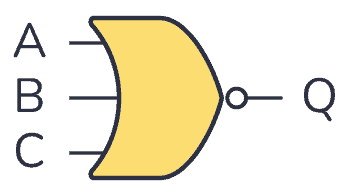
NOR gates can have more than two inputs. But no matter how many inputs it has, it will only give out a HIGH or logic “1” if all its inputs are LOW. As soon as one of the inputs goes HIGH, the output goes LOW.
2-input NOR Gate Truth Table
| Input A | Input B | Output Q |
|---|---|---|
| 0 | 0 | 1 |
| 0 | 1 | 0 |
| 1 | 0 | 0 |
| 1 | 1 | 0 |
3-input NOR Gate Truth Table
| Input A | Input B | Input C | Output Q |
|---|---|---|---|
| 0 | 0 | 0 | 1 |
| 0 | 0 | 1 | 0 |
| 0 | 1 | 0 | 0 |
| 0 | 1 | 1 | 0 |
| 1 | 0 | 0 | 0 |
| 1 | 0 | 1 | 0 |
| 1 | 1 | 0 | 0 |
| 1 | 1 | 1 | 0 |
Build a Transistor NOR Gate with RTL
You can build a NOR gate from transistors and resistors. This technique is called resistor-transistor logic (RTL).
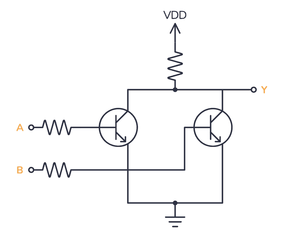
If either A or B is high, one of the transistors turns on. When one of the transistors is turned on, X is pulled low through the transistor.
It’s fun to know how you could build it with transistors and resistors. But it’s not really practical to use that many components just to make a simple logic gate. Luckily, there are many ICs that have NOR gates that you can use out-of-the-box.

Get Our Basic Electronic Components Guide
Learn how the basic electronic components work so that circuit diagrams will start making sense to you.
IC Alternatives with NOR Gates

If you want to experiment and build circuits with NOR gates, you’ll find them in both the 4000 IC series and the 7400 IC series:
- 4001: Four 2-input NOR gates
- 4025: Three 3-input NOR gates
- 4572: One NOR gate (plus a few other gates)
- 74HC02: Four 2-input NOR gates (HC is the family, can also be LS/HCT/…)
- 74HC27: Three 3-input NOR gates (HC is the family, can also be LS/HCT/…)
These should all be available as hobbyist-friendly through-hole chips. Just make sure you buy the DIP package version.
NOR Example Circuit: SR Latch
A typical circuit you can build with two NOR gates is an SR latch. It will remember the last output value it had, so it’s a simple form of memory.
In the following circuit, you can turn the Light-Emitting Diode (LED) on by pressing the On button. The LED will stay on even after you release the button. To turn the LED off, you can press the Off button.
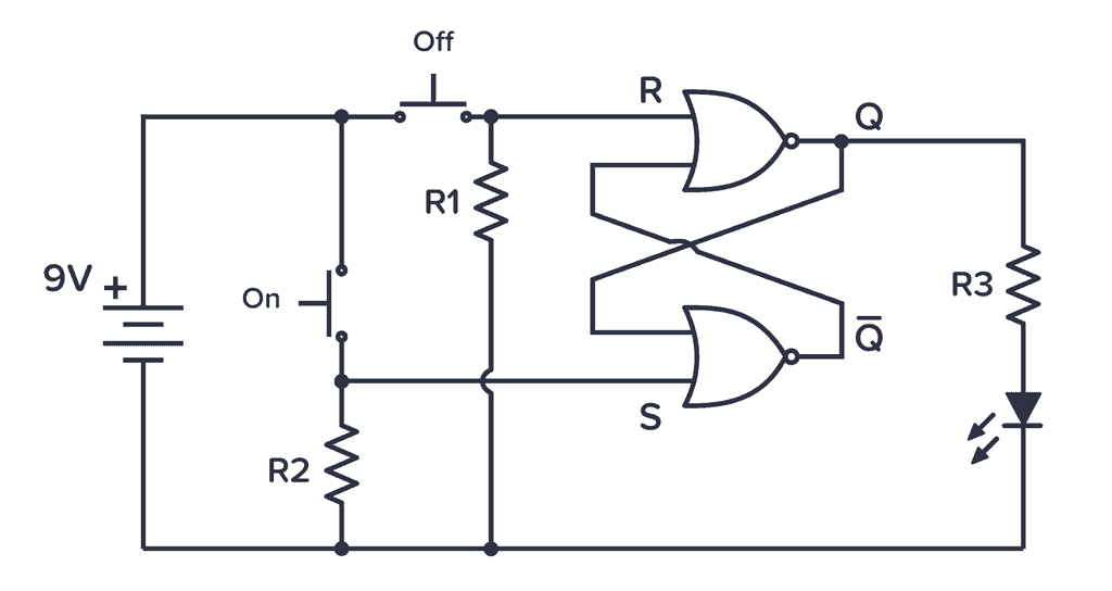
The circuit uses two buttons (ON and OFF) to Set the output to HIGH or Reset the output to LOW. The two gates are set up to create an SR latch that remembers the output for as long as the circuit has power.
More Logic Gates Tutorials

10 Simple Steps to Learn Electronics
Electronics is easy when you know what to focus on and what to ignore. Learn what "the basics" really is and how to learn it fast.