• Skip to primary navigation
  • Skip to main content
  • Skip to primary sidebar
  • Skip to footer
Build Electronic Circuits

Build Electronic Circuits

Electronics explained in a simple way

  • Start Learning
    • Basic Electronics
    • Digital Electronics
    • Circuits
    • Practical Skills
      • Printed Circuit Boards
    • Microcontrollers
      • Arduino
    • Maker Lifestyle
      • Podcast
  • About Me
  • Blog
  • Products
  • Contact
You are here: Home / Basic Electronics / AC vs DC: The difference between alternating and direct current

AC vs DC: The difference between alternating and direct current

January 29, 2020 By Øyvind Nydal Dahl 7 Comments

The difference between Alternating Current (AC) and Direct Current (DC) is simple: AC vs DC comes down to how the current flows. AC is a current that alternates its direction. It goes back and forth continuously. DC is a current that flows in one direction.

Current flow in a DC circuit:
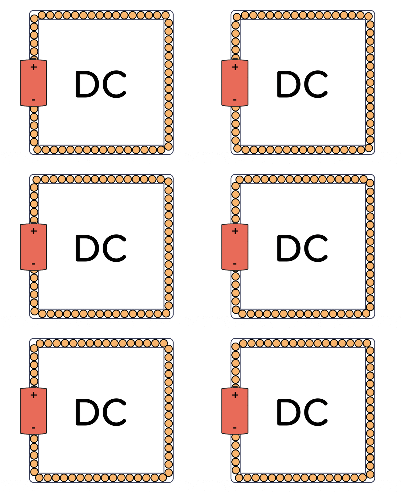
Animated gif that shows the flow of current in a DC circuit

For example, a battery provides direct current. The current only flows one way out of a battery.

The current flow in an AC circuit:
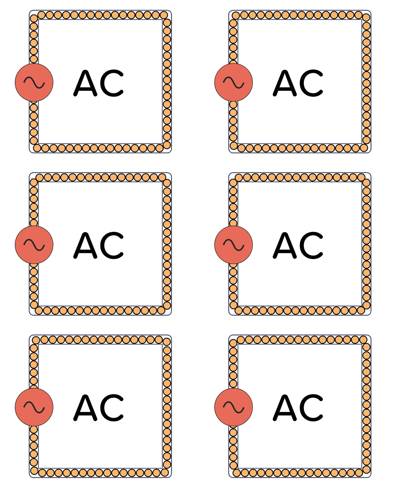
Animated gif that shows the flow of current in an AC circuit

In your wall sockets, you have AC. The current keeps changing direction about 50 to 60 times per second. But for many things, you have adapters that convert it into DC before it is used by a circuit.

(Although, it could as well have been DC in our walls if Edison had won the AC vs DC war back in the late 1800s against Tesla.)

AC vs DC in circuits

You usually need DC to power most things in electronics. I’ve never had the need for a power supply that outputs AC.

But you might find that you have AC in parts of your circuit. For example in audio circuits, radio circuits, or in power supplies.

The AC part is usually either a signal that represents something, like sound. Or an oscillating voltage to send a signal out into the field, like a radio transmitter.

Learn Electronics

If you’re looking to learn electronics, I recommend you focus on learning DC circuits. Knowing what AC is, is great to know. But most of the AC circuit lessons I’ve seen out there are focused on mathematical formulas – and don’t need it until you get to a more advanced level in electronics.

If you want to learn electronics from scratch, you’re invited to join us over at Ohmify. With more than 300 lessons to choose from and a friendly community of like-minded people to help you. And at the Ohmify forum, no question is too basic.

What are your biggest questions when it comes to AC vs DC? Let me know in the comments below.

Filed Under: Basic Electronics

Reader Interactions

Comments


  1. Chris Patrick Augustine says

    February 26, 2020

    This is great and the diagrams need to be further fleshed ot and not just in a single line format. A lot of people think of a circuit as a single electron train going through the wire. No it is “pressure” from one to the next like a train of cars. The same thing with AC and this took a while for me to get my hands around but once understood then you know what neutral does.

    This is all pressure not a real flow. Voltage is pressure!

    And now scientists are talking about the electrons in copper as pseudo electromagnetic particles (they are not part of a photon in copper or other conductor). You do have free range electrons such as lightening.

    Science has really progressed!

    Reply

  2. Teslafan says

    April 27, 2020

    This video also has an interesting information about Alternating current and Direct current.

    https://mega.nz/#!Q6RQharK!VukO-8fgA7C-8hjDeDNucFq1tFchM8KnV8Cb3T-x1rY

    Reply

    • admin says

      May 1, 2020

      The DC animation is a bit misleading as it looks like the battery is spewing electrons into an empty tube. And it looks like the current becomes lower throughout the circuit. But in reality, the “tube”, or the wire, is always filled with electrons, even when no current is present. And the current is always the same everywhere in the circuit.

      Reply

      • Teslafan says

        May 3, 2020

        I am sorry but I am not completely agree with you, current is not always the same everywhere in the circuit. The farther the current (the amount of electrons flowing) goes through a conductive wire, the more it decreases due to the resistance present in the wire.

        Check this video out.

        https://mega.nz/#!Jv5FiK4D!CNzwkgE6GfmiEAilB7KKMlHbeBZu3DE3h4-08NO2itw

        This is what I learnt from these two videos especially from you.

        Reply

        • admin says

          May 3, 2020

          That’s a common misconception. But you don’t have to take my word for it. Just get yourself a multimeter and try measuring the current coming out from the battery on the plus side and compare it to the current going back into the battery on the minus side. It’s the same. You can add as much resistance as you want in between. The current is the same in the beginning and in the end. A resistance (either in a wire or from a resistor) will reduce the current in the whole circuit.

          Voltage, on the other hand, will drop across the resistive elements throughout the circuit.

          Note that this is for series circuits where the current only have one path to take. If you add more paths, the current will divide into the different paths, but if you measure the current going out from the battery at the plus side and compare it with the current going back into the battery on the minus side, you’ll see that it’s the same no matter how complex your circuit is.

          Reply

          • Teslafan says

            May 4, 2020

            Does this mean that in the second video I posted, It is shown that each light bulb is producing different amount of light but in reality all the light bulbs will produce the same amount of light. I guess your answer is yes as I have just built and tested a series circuit on a breadboard using leds and a resistor and I came to know that the video explaination is wrong.


          • admin says

            May 8, 2020

            In that video, the lights were connected in parallel. So there are multiple paths for the current to flow. With 0 ohms resistance in the wires, and equal resistance in every light, they would light up equally.

            But lights connected in parallel, with resistance in the wires between them (like you will have in long wires shown in the video), they will have a voltage drop in the wires. So you no longer have a series connection, but a mix of parallel and series-connected components. The current will be different depending on which path you’re in.

            But the current will be the same if you compare the starting path and the ending path. So you still have the same current going into the circuit as you have going out.

Leave a Reply Cancel reply

Your email address will not be published. Required fields are marked *

Primary Sidebar

Search:

Footer

Topics

  • Basic Electronics
  • Digital Electronics
  • Circuits
  • Practical Skills
  • Microcontrollers
  • Maker Lifestyle
  • Newsletter Archive

Social:

  • Facebook
  • Twitter
  • YouTube

Copyright © 2021 · Ohmify AS · Terms and Conditions · Privacy Policy