This power supply circuit is easy to build and cheap. And it requires only 5 components.
I have built many circuits in my life, but this is actually the first time I’ve built a power supply circuit from scratch.
The final project I wanted to build was a wall adapter with a USB socket to charge my iPhone. But first I wanted to start by creating a simple circuit that converts from the main power voltage, 220V or 110V, to 5V.
As I’m in Australia while writing this, and the voltage here is 220V, I built this with 220V in mind. But it’s very easy to convert to 110V instead by switching one connection (or one component).
Caution: Do NOT connect anything you make yourself to the power mains if you are not 100% sure about what you are doing. Doing it wrong can cause serious damage, even death. Use the information provided here at your own risk.
If you want a perfectly safe and extremely useful power supply circuit, you should check out this portable USB charger that I built. It even includes a downloadable step-by-step tutorial on how to build it yourself.
Designing The Power Supply Circuit
I want to base the power supply circuit around the LM7805 voltage regulator because it’s an easy-to-find chip that is simple to use. This component will give a stable output voltage of 5V up to 1.5 A.
I can easily figure out how to use the LM7805 by looking in its datasheet.

Get Our Basic Electronic Components Guide
Learn how the basic electronic components work so that circuit diagrams will start making sense to you.
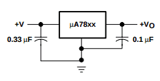
From the datasheet I found this little circuit:
Choosing Capacitor Values
The above image shows the voltage regulator with a 0.33 µF capacitor on the input and a 0.1 µF on the output. It’s hard to find a good source of info on these capacitor values, but according to this Q&A there’s nothing magical about these values.
There are a lot of opinions on the web about these capacitors. Some suggest 0.1 µF capacitors, and others suggest 100 µF capacitors. And some suggest using both a 0.1 µF and a 100 µF capacitor in parallel.
The values you should use depend on a lot of factors. For example how long the wires are going to be. But this article is about how to build a simple power supply circuit, so let’s not complicate things. Probably, almost any capacitor value will work. It will probably even work without capacitors.
For the sake of making the output voltage “a little bit stable”, I’m going to use a 1 µF capacitor on the output. I’ll skip the input capacitor because there will be a capacitor in this position anyway – just keep reading.
Converting From 220V
The datasheet also says that it needs between 7V and 25V to work correctly. So, I only need to add a few components that convert 220V (or 110V) AC to a DC voltage that stays between 7V and 25V.
This is relatively easy. I’ll just add a transformer that transforms the voltage down to for example around 12V. Then I’ll feed this AC voltage into a bridge rectifier to rectify it.
And I’ll use a large capacitor on the output to keep the voltage above the necessary 7V at all times. This capacitor value isn’t critical. I’ve seen many power supply circuit designs that use 470 or 1000 µF, so I’ll try 470 µF for now.
The Power Supply Circuit Diagram
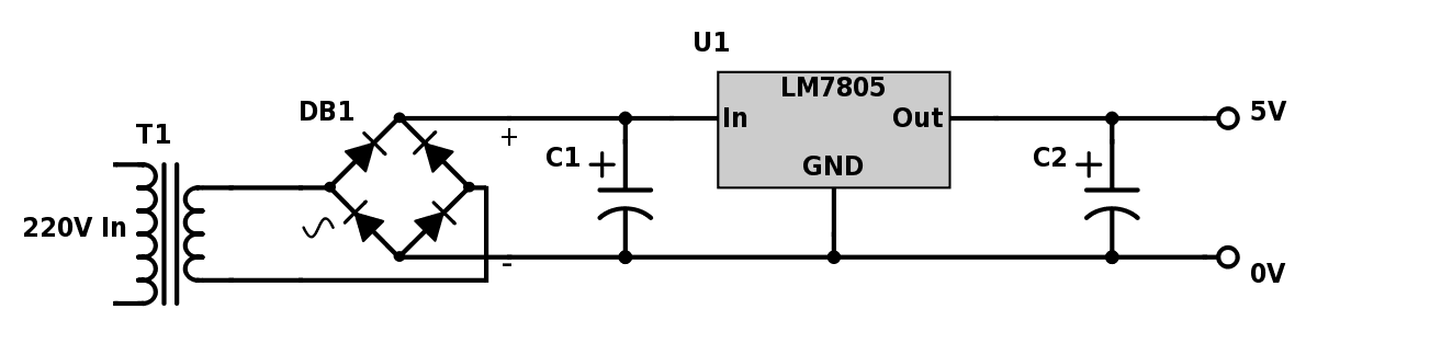
So, the final circuit looks like this:
Parts List
| Part | Value | Description |
|---|---|---|
| T1 | 220V (or 110V) to 12V | Transformer |
| DB1 | Diode Bridge Rectifier | |
| C1 | 470 µF (20V and upwards) | Capacitor |
| C2 | 1 µF (10V and upwards) | Capacitor |
| U1 | 7805 | Voltage Regulator |
The total cost of the components is about $12-15. The most expensive component is the transformer (about $10).
Finding Components For The Circuit
When I’m not sure how to choose components for a circuit, I usually go to online electronics stores for hobbyists and look at their options. These stores usually stock components that should work in a standard power supply without any special requirements.
In Australia, Jaycar is a nice option.
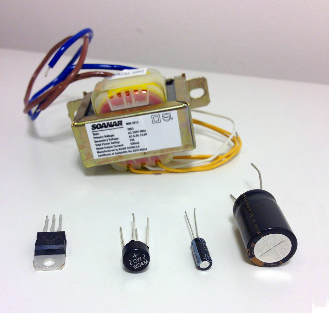
A quick search on “transformer” on Jaycar gives me several options. The input voltage needs to be around 220V and the output around 12V. After a quick scan of their options and prices, I decided on this one:
https://www.jaycar.com.au/12-6v-ct-7va-500ma-centre-tapped-type-2853-transformer/p/MM2013
The transformer has a center tap on the output side which I can ignore.
This one is for 220V. If you live in a country with 110V the stores in your country will probably have the correct version for you. Click here to check out my list of online stores.
Then I need a rectifier. We can use 4 power diodes (ex 1N4007), or a bridge rectifier (which is basically four diodes built into one component). The cheapest option that pops up when searching for a bridge rectifier on Jaycar is this one:
https://www.jaycar.com.au/w04-1-5a-400v-bridge-rectifier/p/ZR1304
The Finished Power Supply Circuit
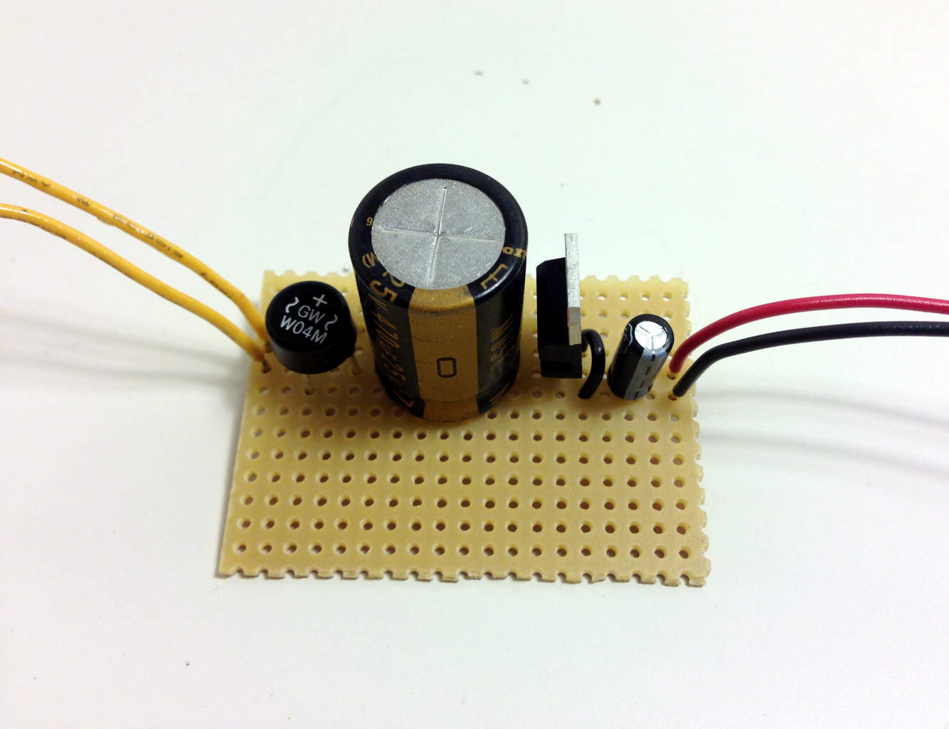
This is an easy circuit to solder onto a prototyping board. Here’s the prototype I built:
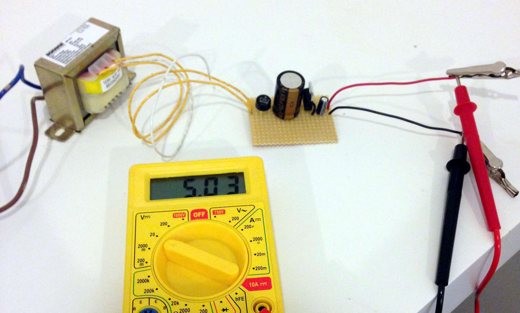
Reminder: Do not connect anything you build yourself to the power mains unless you are 100% sure about what you are doing. Use the information provided here at your own risk.
Did You Build It?
Did you build this circuit? What’s your experience? Anything you struggled with? Let me know in the comments below how it went.
More Power Supplies Tutorials
Get Our Basic Electronic Components Guide
Learn how the basic electronic components work so that circuit diagrams will start making sense to you.

Thank you. I have built 12 and 5 volt DC power supply by same method you discussed above.
Great =)
Oyvind
Pls how do I go about connecting the bridge Diode
When I search on google for a 110 v transformer, the results are always for power supplies
rather than just transformers.
Can you please offer a suggestion for a suitable transformer in US ?
Hi,
I did a search on Jameco.com – and found this one that should be suitable:
http://www.jameco.com/z/P-8657-R-Power-Transformer-12V-2A-117VAC-Wire-Leads_221400.html
Best,
Oyvind
Thanks for sharing such a nice article. i love your writing. your idea is mind blowing that’s why i would like to appreciate your work.
I have not built this circuit. But two months ago I built a mobile charger that works on any smart phone including apple ipods, iphones & ipads. I used am LM7805 with one USB type A connector & four resistors wgich is required to charge any apple ipod, iphone & ipad. It also charges any other brands of smart phone. I have tested it on friends mobile phones & those that have ipads or other tablets. They can’t believe that my cost is way cheaper than any apple chargers. I don’t use any transformer as I have designed it to use Solar panels (12V 10W to 200W) or any wall charger ACDC from 9V upwards. I have also bulit a Variable power suppky from 1.2V to 22V using LM317T regulator.
Nice!
Do you use any capacitors or do you find it working fine without capacitors?
Best,
Oyvind
Hi! I would like to see the circuit diagram, please. I’ll be using it for our research (school requirement) Thanks and have a good day! :)
I have an old van that I would like to install this in. Since the vehicles in the u.s. run on 12 volts I wouldn’t need a Transformer but probably should use the full wave rectifier. Any ideas?
Hi,
You’re right. In this case, you wouldn’t need a transformer. But the 12V is already a DC voltage, so you wouldn’t need the rectifier either.
I would use the capacitors, for stability’s sake. But don’t worry too much about the exact values.
Best,
Oyvind
How do you make it so you can adjust the current (constant current) of the 12v source to power 12v leds?
Unless you have some special type of LEDs, you don’t use a constant current source for 12V LEDs. You provide 12V from a voltage source that can provide at least the current your LEDs need.
For example, if your LEDs need 50 mA you need a 12V voltage source that can provide at least 50 mA. But a voltage source of 5A will also work perfectly fine. The LEDs only pull the current they need (as long as they have an internal resistor – otherwise you have to provide the resistor).
I have build power supply alot for my projects, what I find fascinating about it the pieces you put together to get your stabilised dc from your ac. At it was a challenge, because any reversing of components like bridge rectifier diode, capacitor polarity will render a fault it… Thus details need to paid
Building power supply is quite fundamental for any electronic hobbyist, yet its a do or die skill that one need to have, cuz it set that freedom to manipulate power supply. Oyvind your application of electronic here is remarkable, it just show how cost effective it is to hve such a skill.
A challenge I wanna take t my side is building an inverter, a device for converting Dc to Ac.
FIngertips Electronics
Chris
Mains Wiring:
I think it is very irresponsible of you to post this, and to be embacking on building a mobile phone charger. Clearly, you don’t know what you’re doing “…but this is actually the first time I’ve built a power supply circuit from scratch.” If you actually knew what you were doing, you wouldn’t be saying “Caution: Do NOT connect anything you make yourself to the power mains if you are not 100% sure about what you are doing.”
You would instead be posting a detailed description of the things you need to know and do when working with mains power. Like securely mounting components on proper chassis, including a fuse on the mains side of the transformer, using a double pole switch so that you know that you aways switch line and neutral together. In Australia, evey power point has a earth pin. So you make sure that the metal chassis and cabinet are earthed. And you do use a metal cabinet. If there is some sort of failure that results in a live wire coming in contact with the cabinet, the current goes to earth and the fuse blows.
If you use a plastic case with externally exposed metal parts – think mounting screw heads – you’ve made a death trap.
I could go on. The photo of a multimeter with probe tips near a mains circuit is quite horrifying.
People don’t go around intentionally electrocuting themselves or setting things on fire with their mains powered projects. They just don’t know how to approach this stuff safely. The probes and alligator clips on the $9 Jaycar multimeter are an accident waiting to happen.
Lithium Batteries:
Lithium chemistry batteries are dangerous. Period. I don’t need to explain this, just look at this link
.
Odds are Samsung’s current problems are something to do with their batteries or their battery management circuits. If you really want to make a phone charger for yourself, read this application note from Microchip: http://ww1.microchip.com/downloads/en/AppNotes/00947a.pdf.
It explains everything that needs to happen when charging lithium batteries and includes a simple circuit diagram for a charger that is managed by one of their charge controller chips.
Please do some research before you start posting stuff on the Internet. I you start with how to
safely construct a mains powered device of any kind.
Oooh looks like the dropout electrician has arrived!
Lol, yeah mate. Multimeter probes near a mains circuit are a real risk…
You do know you can stick a multimeter into your power outlet, right?
Also, this is a power supply circuit, not a lithium charging circuit. Most phone chargers only supply output power, the devices themselves manage the battery charging.
There is no switch either, so I have no idea why you mention needing a double pole switch.
This whole project is just a simple circuit for demonstration purposes, which you can incorporate into a larger project. There’s no grounded enclosure because the rest of the device it’s going to be used with hasn’t been built yet.
OK, So your comment software killed the link. Plug this into Google:
third-party batteries site:www.howtogeek.com
The first link that comes up tells the story.
Please tell me about the circuit for the power bank because it is the portable charger for phones
Well for me that was probably harsh Russell, i understand the fact that safety must not be neglected in whatever we do but i also know that there are better ways to say that. Thanks at Oyvind.
Thanks for the information, seems like a really good project. Do you have any suggestions on how to build a variable power supply, say 5 – 24 volts. I believe it would be so much cheaper to build one then to buy one. Your help will be appreciated Oyvind
Hey Bob,
There are voltage regulators for variable output too. Like the lm317. Check out this circuit:
http://www.circuitstoday.com/few-lm317-voltage-regulator-circuits
Best,
Oyvind
Wow, thanks for the input, that is just what I need.
It’s so amazing, I did mine and it’s working perfectly with the above components and with the same procedure stated above.
That’s great =)
Oyvind
I need a 24 Volt DC output supply as charger for my Sanyo Enacle power-assist bike as I do not actually have the original charger when I bought this second hand bike from surplus store. I want to build the needed charger myself by using 3A center-tap 24 V output xformer, question is: do I need to have the same (value) component mentioned above with this 24 VDC output or will it matter? If so, can you email me the simple schematic diagram and the component value in building 24 VDC regulated output charger by using 3A Xformer (12-0-12).
You need a different voltage regulator than the one in this diagram. A quick search gave me the 7824 chip as an option. Look in it’s datasheet to learn about it. You can probably use the same value for the other components.
Best,
Oyvind
Using the center tap with a switch could make it 110/220 switchable for those who travel.
That’s true. But only if the center tap is on the input side.
Oyvind
Hi Oyvind!
I’m going to make a circuit that use Arduino to control 5 solenoid valve 12VDC and 2 motor 12VDC.
My problem is that my adapter 220VAC – 12VAC can’t supply enough power for these 7 things.
I wonder should I reuse my old ATX power supply of PC or build a new one.
Can you suggest what I should do?
Thanks,
TADT.
Hi Thien!
That’s cool =)
I would suggest reusing your ATX power supply. Easier, cheaper and it let’s you focus on your Arduino project.
Best,
Oyvind
Oh, thank you very much Oyvind!
Best,
TADT
Thank you for giving me the opportunity to visit this impressive website. There is plenty of valuable info listed on this site.
I have seen a lot of tricks. It is too much to absorb at once, thus I definitely will return to view more.
Hi Oyvind. Can u suggest a safest xforless pwr supply that can give an sdjustable output of 1.2 to 50V DC on a 230V/ 60Hertz input
Thanks,
Ding (i am an avid follower of yours from the Manila)
Hi Ding,
I don’t have that. But maybe you can start your research here and see what you’ll find: http://www.daycounter.com/Circuits/Transformerless-Power-Supplies/Transformerless-Power-Supplies.phtml
Best,
Oyvind
thanks very much for this information which is really helping me to build my own power supply.
Sir I have a a printer’s power supply 32v I have an amplifier circuit board it requires 12v 3amp power supply., so guide me how to reduce 32v to 12v supply
Hello. im kinda new into electronics, can you explain why you choose 470uf capacitor in that circuit. i understand the part in the 20V because its the Max. voltage it can store, i just want to know why you choose 470uf
thanks you
The 20V is the maximum voltage drop it can have without the risk of damaging it.
It’s the 470µF that tells you about its ability to store energy. The larger, the more energy it can store.
What is your pcb lay out
What is you pcb design for this
Simplest powersupply
Hi, I haven’t made a PCB layout for this. But it should be pretty easy if you want to have a go at it. My preferred software to do this is kicad, but if you want something really simple (but less powerful) you can try Fritzing.
Best,
Oyvind
Hi, can u tell me what excatly capacitors did you chose?
Hi, I used electrolytic capacitors.
Best,
Oyvind
Hi
i need to design a power supply the output of power is (+9v , -9v , +5v) in one circuit
help me please