Build this portable USB charger circuit, and you’ll always have access to a charger.
Imagine a beautiful summer day. You’re on your way to meet friends for a picnic in the park. But, the park is huge and full of people. Since you don’t know where exactly your friends are, you pick up your phone to call them.
But as you dial the number, the battery on your phone dies…
Ahhh!
With this portable USB charger circuit, there’s no need to worry. Just drop by a supermarket nearby and pick up some standard batteries to recharge your phone on-the-go.
Update: Back in 2017 our phones required much less current than today. So this design might not work if you have a newer phone.
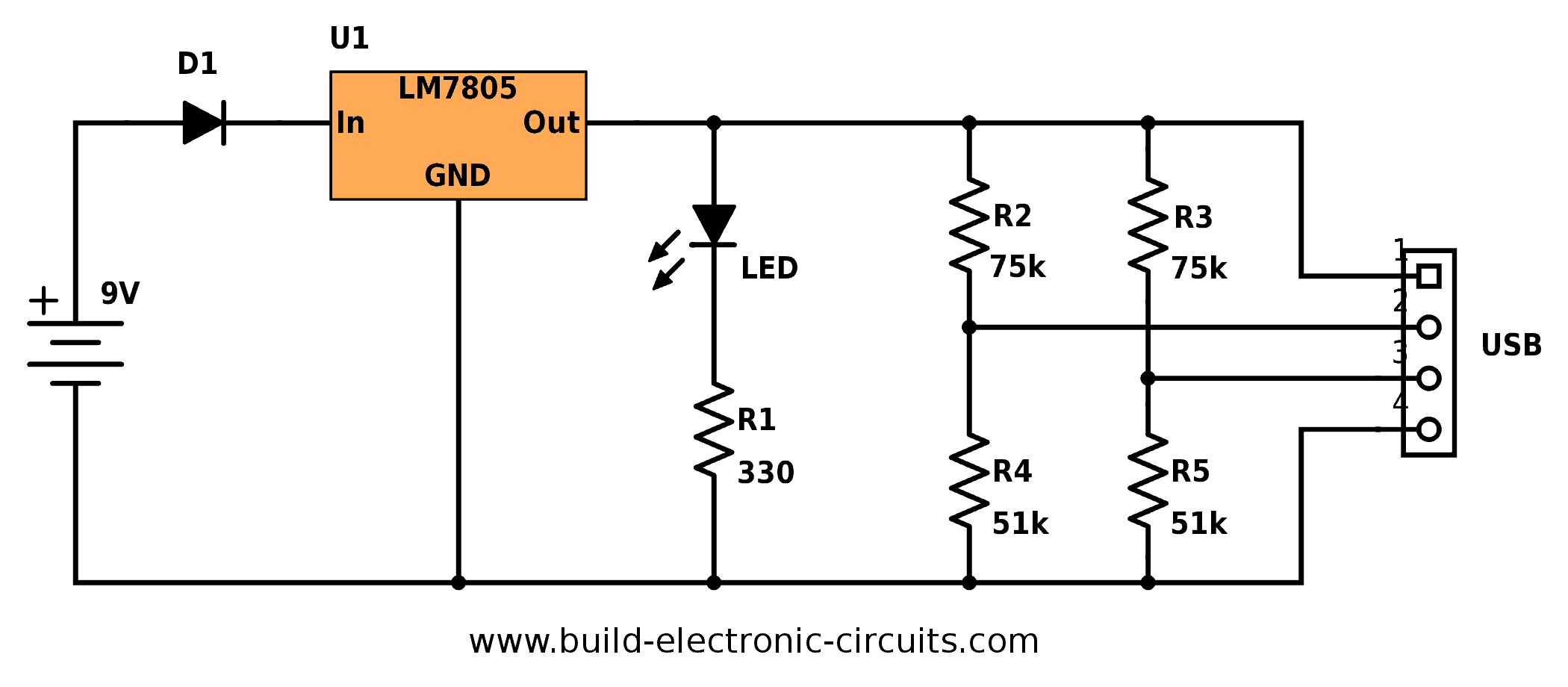
Portable USB Charger Circuit Diagram
Here’s the circuit diagram:
Parts List
| Part | Value | Description |
|---|---|---|
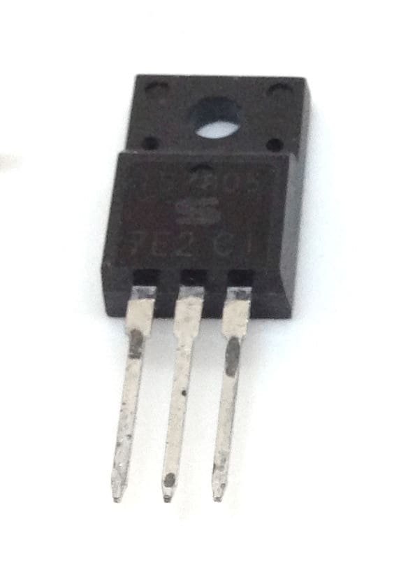
| U1 | 7805 | Voltage Regulator |
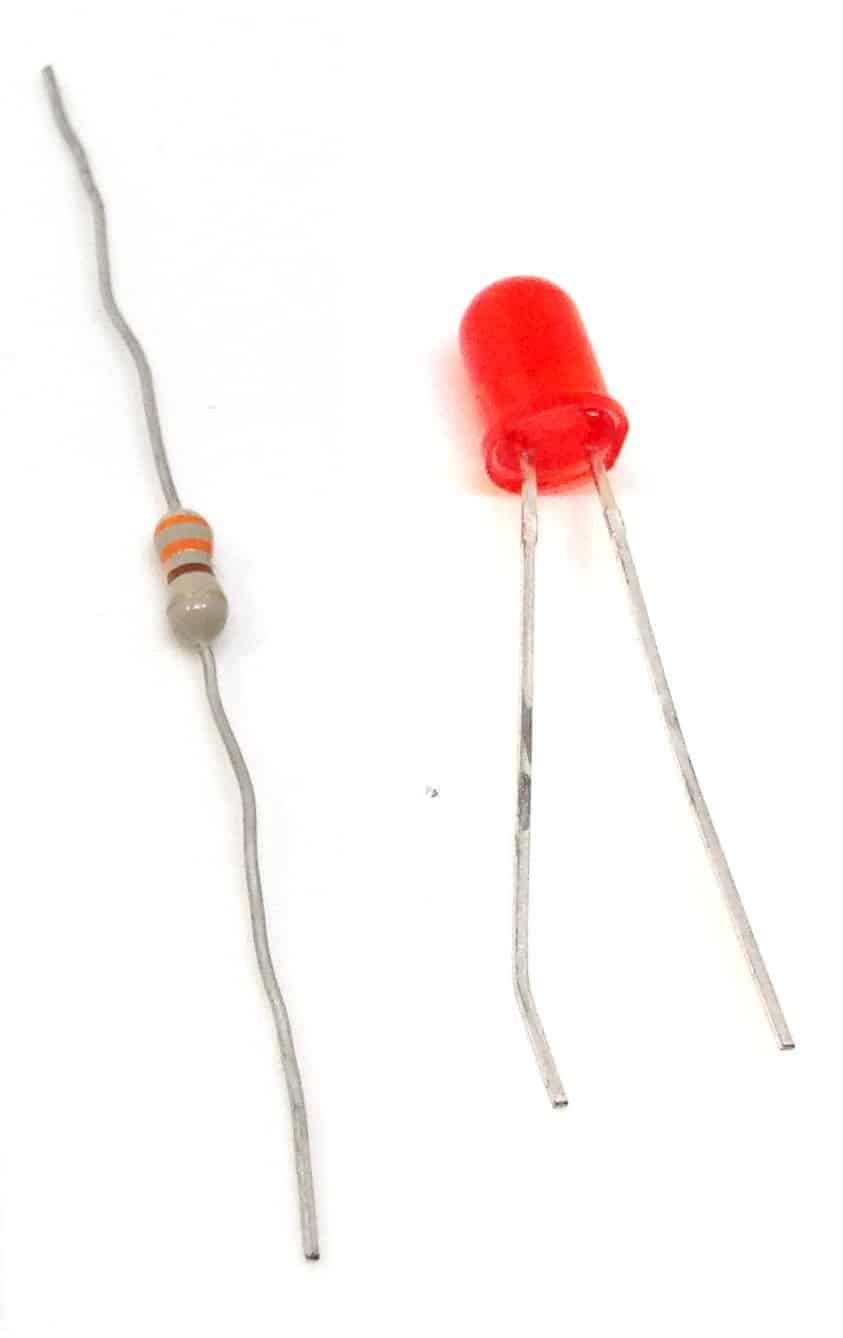
| LED | Standard Output | Light-Emitting Diode |
| R1 | 330 Ω | Resistor |
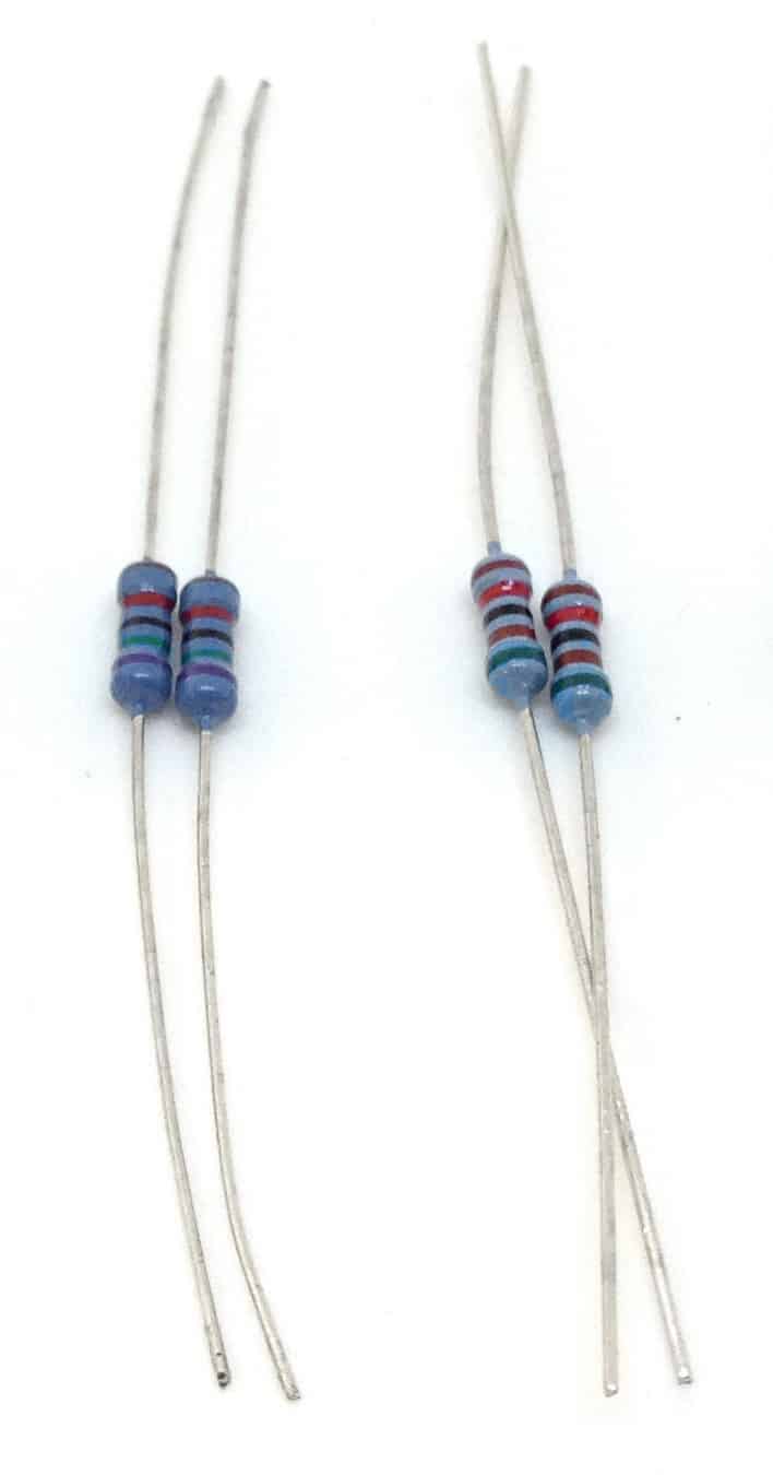
| R2 | 75 kΩ | Resistor |
| R3 | 75 kΩ | Resistor |
| R4 | 51 kΩ | Resistor |
| R5 | 51 kΩ | Resistor |
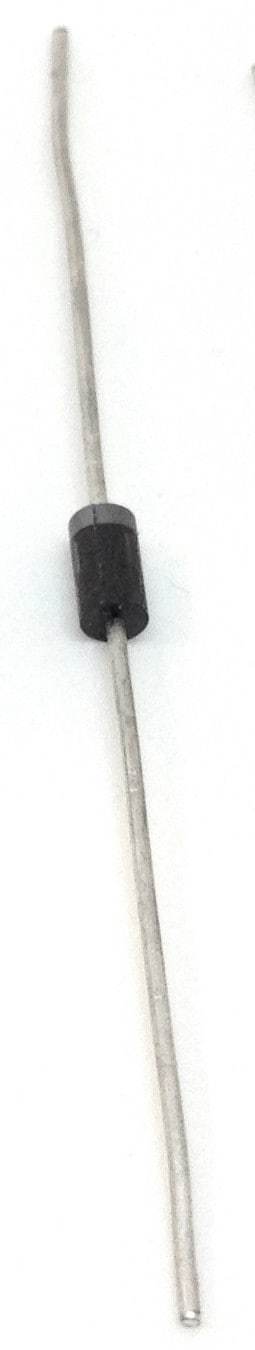
| D1 | 1N4001-4007 | Rectifier Diode |
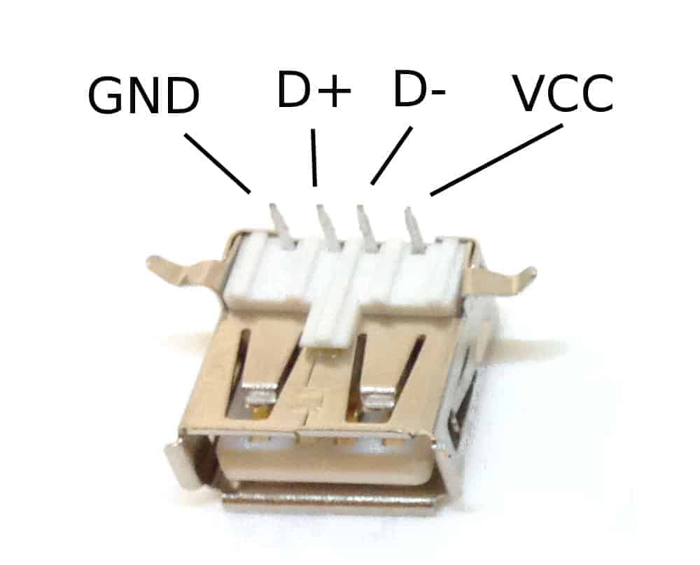
| USB | Type A Socket | Solderable |
| – | 6xAA, 6xAAA or 9V | Battery Connector |
I’ve created a resource page to make it easy for you to find components. Click here to see where you can get everything you need to build this circuit.
Build Something Practical This Evening
Download this tutorial that shows you step by step how to build an old-school USB charger for your mobile.
How The Circuit Works
The circuit is based around the LM7805 chip. It’s a voltage regulator that takes an input of between 7V to around 30V and gives out 5V with up to 1A of current.
To see if the charger is working or not, I’ve included an LED and a 330 Ω resistor between 5V and the minus of the battery. The circuit will work perfectly fine without these also.
The resistors R2 to R5 set the voltage levels on the data lines to specific voltages. These voltages ensure that the device knows what current to use for charging. I got the values for these resistors from an Adafruit article where they opened an iPhone charger to see how it worked. These values will make an iPhone and many other devices charge with 500 mA.
The rectifier diode D1 makes sure you don’t damage the circuit if you connect plus and minus the wrong way. It also reduces the voltage by 1V, which means you need at least 8V in for the charger to work.
It’s not really necessary to have this diode. If you’re going to solder the plus and minus leads to the board, I’m sure you’ll double-check the connection before testing. But, with 9V input it’s a good thing to reduce the voltage to the voltage regulator anyway to reduce the heat.
Also, it makes it possible to use a DC socket for connecting a range of different inputs without worrying about plus and minus being correct.
The voltage regulator can still get too hot and shut down, even with this diode. If you find that this happens a lot, you can solve it by adding a clip-on heatsink for TO-220.
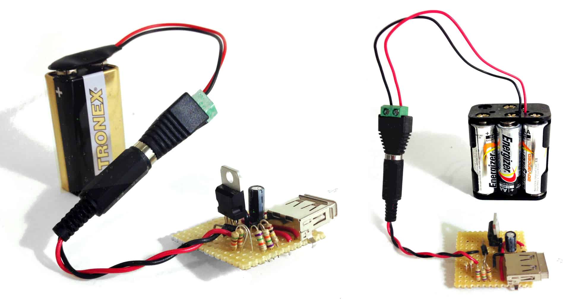
The USB charger circuit works from 6 AA batteries, 6 AAA batteries, or a 9V battery. All these batteries are fairly simple to find in most supermarkets.
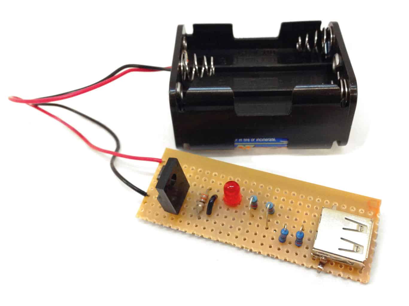
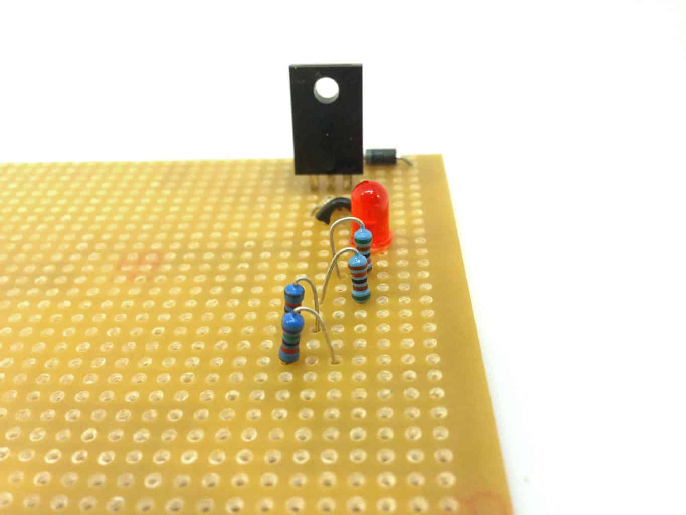
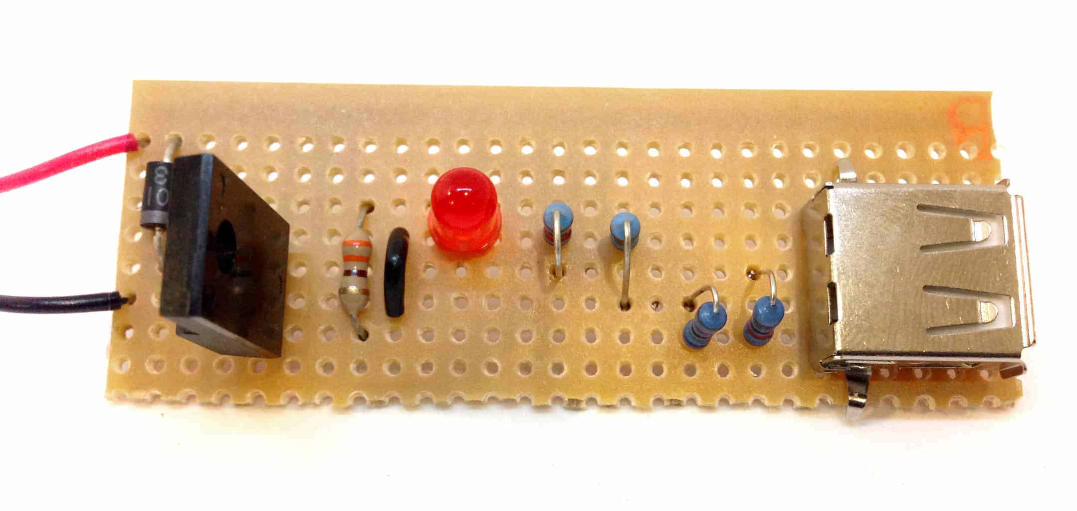
How To Build The Charger Circuit
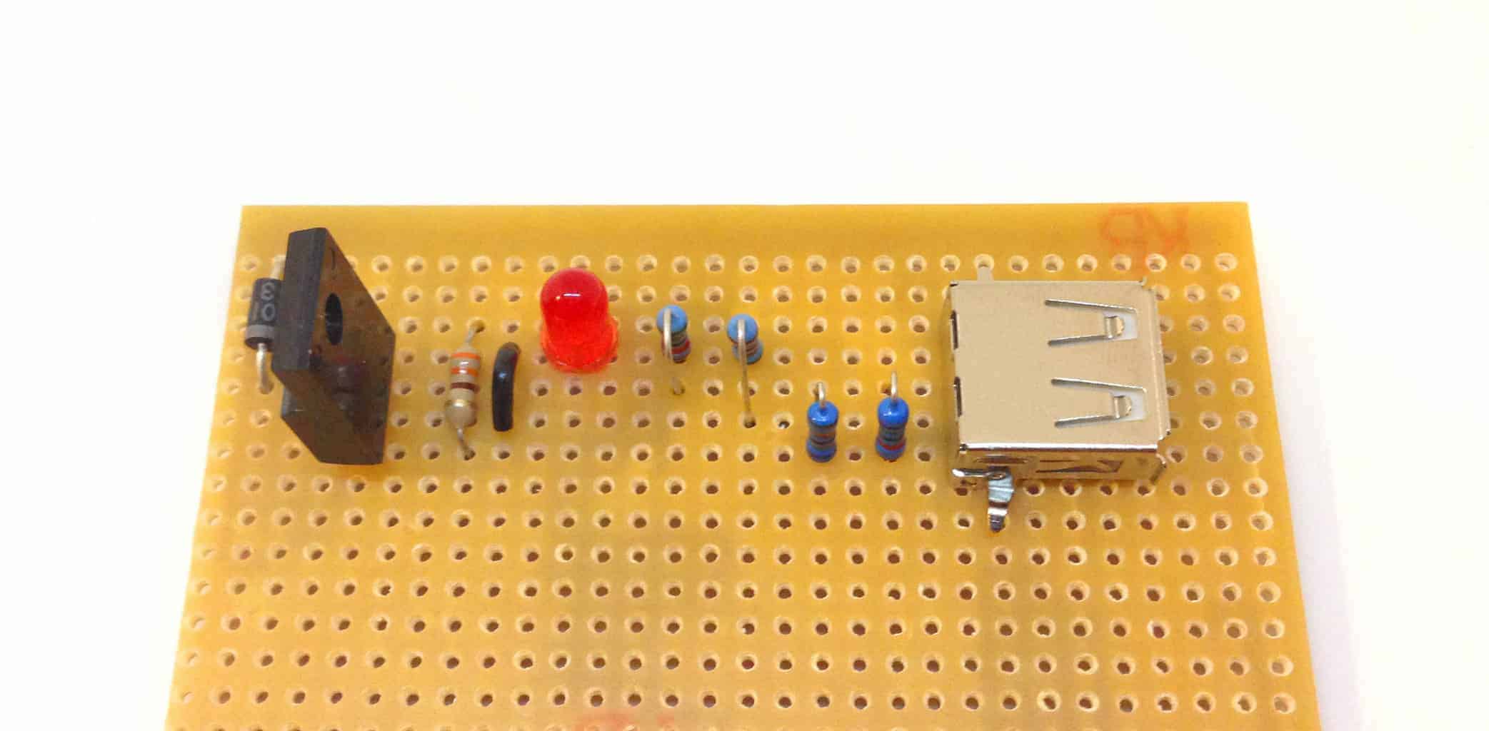
This circuit is fairly easy to build. You only need 7 components. It’s perfect for soldering onto a stripboard.
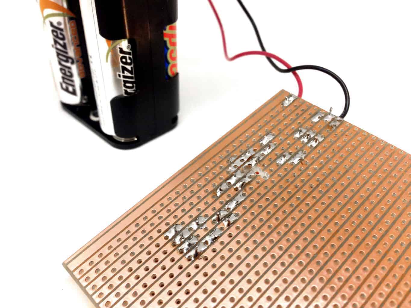
I’ve created a PDF tutorial with step-by-step instructions for building this portable USB charger.
Modifications
If you want to use a different type of battery, just switch to a different battery connector. Or even better, use a standard DC input socket so that you can connect it to standard DC wall adapters. Then connect DC plugs to battery packs for AA, AAA and 9V batteries to have a whole range of charging possibilities.
You can also use solar panel chargers on a sunny day.
Did You Build It?
Let me know how it went in the comment field below. Questions are welcome!
More Power Supplies Tutorials
Build Something Practical This Evening
Download this tutorial that shows you step by step how to build an old-school USB charger for your mobile.
Thank u for the article. However, the 7805 should not be used due to the heat it outs out. Try a MC34063 chip instead.
Thanks for your comment Mike!
I suggest 7805 for beginners because it makes the circuit pretty easy to build. But you’re right about the heating problem.
I haven’t tried the MC34063 chip, but looks like a good option for those who want to make an improved design!
Best,
Oyvind
Mr, Can you show to me about MC34063 chip . sir please.
Could I build this on a breadboard
Yes, but the USB socket I use doesn’t fit on a breadboard. I suggest using a usb-socket with cable, then you can plug the wires into the breadboard.
Oyvind
I think u ihave all components but for the 7805 in my couple of boxes of starter kits. ill source 1 from on line and build on a bread board then try my soldering skills again by building again on sum track board. thank u. for your websites blogs youtube tutorials etc these have got me into learning electronics, since I became disabled recently. great things you teach oyvind. thank you..wayne..
Hey Wayne,
Did your circuit work, because I tried to do it on a breadboard and only the LED work, and i dont see my error. So, I was wondering if you had a photo of your circuit so I could see where my mistake was.
Hello Oyvind I build your circuit on a breadboard and it worked but it only charge my IPhone for a minute and the led stays on and I used a heat sink for the regulator but I don’t understand why it stop charging, is there a way I can make this portable charger to charge my iPhone from 0-100%, can I add capacitors on the circuit
As you mentioned that It is really not necessary to use rectifier diode. But i think if we don’t use Diode here then the current will work Reverse biased when we connect our phone. Instead it works opposite when batteries are low in the current our mobile gives them current for recharging and we don’t want this. Please let me know is i am Right or Wrong?
Hey Jagjot,
For this to happen, the input battery voltage would have to be lower than 5V. But even if that happened, I don’t know if the 7805 regulator is built in such a way that it’s possible. Could be. But, the third thing is that the charging circuit inside the phone would have to be designed in such a way that it was possible to get power out of it. I don’t think that’s the case.
Best,
Oyvind
In case of otg capable phone.
What you think??.
It will reverse charge unless the battery voltage less than phone. But 7805 dont let to be happend
Thanks for this free knowledge stuff, I am grateful.
I’m glad you like it!
Oyvind
Please guide me through the modifications required for getting an output of 2.1 A keeping voltage as 5 V
To charge with 2.1A you need these voltages on the data lines:
D+: 2.7V
D-: 2.0V
If you replace R2 with a 43K ohm resistor you should get those values.
Keep in mind the 7805 will get very hot with this much current. You’ll need a big heat sink. Also, standard AA batteries are not able to give out 2.1A for a very long time.
Best,
Oyvind
7805 max current is only 1 A. But you can reach 2 A with 2 7805 in parallel. And a lot of heat, too.
Thank you :) I really enjoyed it.
Your explanations are simple, yet technical and up to the point.
Glad you liked it! =)
Oyvind
Thanks !
I love this project and the article about “How the Circuit Works” really good and useful and amazingly easy to undestand….
Two Thumbs Up!!!
Great =)
Oyvind
I really appreciate all you do you made me proud of my self, you always give understandable explanation,). Thanks oyvind for your great work.
Great to hear! =)
Hi oyvind, Im kaizer from South Africa, I ve been trying to contact you regarding the Ebook I purchased from you recently several times but up to no avail. The book is entitled’ Get started with Electronics’ and it cost me 15 dollars,but the problem is when I tried to download it after purchasing it, the download failed completely. I am frustrated and dont know what to do anymore, other items I purchased from you downloaded succsessfully. Then, what could be wrong with this one? Please advise. Could it be the size of the file maybe?
Hi Bethuel,
I’ve sent you an email. You should be able to download it now.
Best,
Oyvind
Thank you so much Mr. Can I use with Motor Bike battery 12V , 20 A. And , I need the circiut with water proof so can I put in enclose can if possible because of IC heat out. And, is it need more any components for smooth volttage and Ampere. Exemple, any core for output . Please explain me sir.
I hope…
12V in on this circuit will make the 7805 very hot. So you’ll need a good heatsink, or try lowering the voltage.
Best,
Oyvind
Thank you so much, Mr.Oyvind .
First I reduce the voltage till 9V with 7809 and second I will use 7805. Can I use like this, Sir.
Also, I really hope Ebook 10 step to Learning built Electronic but I can’t buy because I am from Myanmar I have no any account to pay and still problem to buy. So, Help me any way. Sir.
Your Faithfully
Bo Bo
That ebook is free =)
Hi,my name is john muthama from kenya.i would like to build a simple audio amplifier ising transistors.could you please send me a circuit that i can use to build this,.thanks
Hey,
Maybe you can find something here:
https://www.build-electronic-circuits.com/free-electronic-circuits
Best,
Oyvind
Dear Oyvind
thanks for this very useful circuit.
I built your phone charger circuit to charge my blackberry 9320 but it only charges the phone for a minute or so then it stops, and you have to plug it out and back in again.
And it doesn’t seem to charge my Smart-Blackberry at all.
Any idea why? I’m using a PP3 battery with the circuit.
PS I managed to fit the whole thing into a 80 x 50 x 25 mm box by placing the resistors underneath the battery holder.
Hey Timothy,
When it stops charging, check if the LED is lit. If it is not, I’m guessing your 7805 is very hot? It has overheating protection and turns off if it gets too hot.
You can solve this by adding a clip on heatsink.
Best,
Oyvind
Think,but i really need componentsI’m frm Liberia.I love to built them repair.
please…help.
can we use a transformer instead of battery..
because i have to make a auto turnoff battery charger in my project
Hi, yes. Check out this article:
https://www.build-electronic-circuits.com/power-supply-circuit/
Best,
Oyvind
Such a great article it inspires me to dear experimenting
Useful circuit, I wish to charger batteries also when returning to home, thanks
wireless usb charger is getting more demands now a days..wireless power transfer is the future technology that can be make a drastic change in communication field..my blog http://www.innovativeeideas.com/
I tried it and it showed the charging signal on my iPhone but its not charging. I measured the current entering the phone its as low as 128mA which cant charge the phone. any suggestion pls?
It could be that your battery is not able to give 500 mA. The resistors indicate to the phone that there is 500mA available, so it tries, but the battery cannot keep up and the voltage goes to 0V. Then it tries again, fails and voltage goes to zero.
If you have a oscilloscope you can measure the 5V output when you’re trying to charge to see if the voltage keeps going up and down between 5V and 0V.
Best,
Oyvind
Sir can i use lithium ion batteries in place of AA batteries
Also i want an output of 2 ampere so what modifications are required and also any way to deal with heating of 7805
The LM7805 usually has a limitation of 1.5A. Maybe you can find a 2A one. To address the problem of heating, use cooling.
Best,
Oyvind
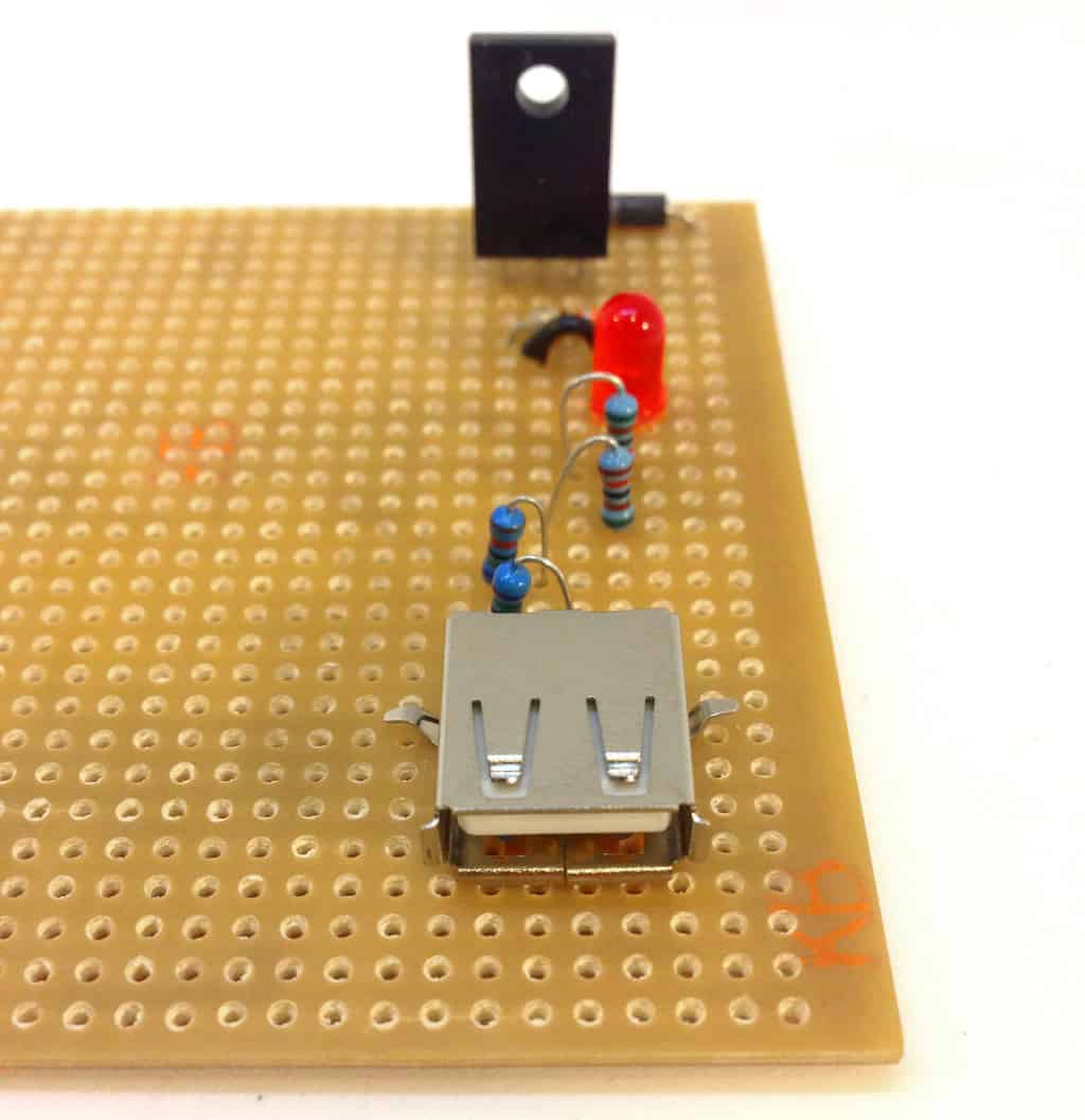
Hi, Øyvind. Congrats for your website. I have a question. In the pictures under the section “Modifications”, the led does not seem to appear but it seems you have placed a capacitor in the board instead. Would you be so kind to explain this susbstitution, please?
I was very happy because I had understood the operation of the whole circuit; however, when I noticed the pictures I refer to where different to the final photo of the charger, I got a bit puzzled.
Thanks in advance¡
Hey Javier,
The picture under modifications shows an older version I made. The point of that picture was to show how you can connect other things. Ignore the other parts on that board as it is an older prototype.
Sorry for making it confusing!
Oyvind
Hi, Øyvind. Thanks for sharing your ideas. I have built the charger and get out 4.98 volts. I’m getting 3.2 volts on the D+ and D-. Can you tell me what I did wrong as I used the components that was specified by you. Will I be able o use the charger as is on my Note 3 and Huawei P8?
Thank you
Regards
Gideon
Hey Gideon,
4.98V is close enough to 5V for it to work.
You should get 2V on the data lines. Sounds like you’ve switched the two resistor values.. But that should give you 3V not 3.2V, so there might be a problem with your resistors.
Best,
Oyvind
how to increase the output current 0.5mA TO 1.5 or 2? So we can charge our mobile fast.
I need 5V 1.55A output please help me,
If there is any better circuit let me know.
Does this work on 11.1 v (3.7×3 nokia battery 1020 mah).
I have a mobile charger and battery li- ion 2000 mah, I want to make power bank, it’s possible?
How come that the output voltage is 5 volts without a load, but when I connect to my phone to charge the output is 4.58? Not stable to 5 volts.
The d+ and d- is 2volts as you mentioned.
Sir, how can I get stable 5v when I’m charging?
Could be that your regulator does not support enough current. What will happen then is that the 5V will be turned on and off really fast, making it look like you have a voltage lower than 5V on the output.
Hi! I want to try to do the picture under your modifications since it has a capacitor. May you list me all the parts for that specific picture on the right under modifcations? Thanks!
Hi! The pictures under modifications are there to show the connector. The circuit in the picture is an older version of the circuit, so ignore that one.
Concerning getting 2.1 A output for fast charging and the 1.0 A output rating of of the LM2805, which would be best (I’m adding the circuit to a 12V solar lantern): a) Putting a 7809 before the 7805 to drop it to 9V before dropping it to 5V to spread the heat load, or b) putting two 7805’s in parallel (perhaps with diodes on their outputs to prevent possible back current) to split the load, or c) put on a humongous heat sink as the current limit is really a temperature limit?
Hi, Øyvind. Thanks so much for this great explanation.
On average, using a 9V battery, for how long would this charger charges phones.
thanks sir.
I can’t able to download as pdf
i have learnt how to make the charger but if i don’t put led, how will the circuit look like
Hi, you have done a good job and i congratulate your good effort. Please i want to construct a lion-ion battery charger with auto cut off. Can you kindly send me the circuit. Will appreciate your anticipated effort.
Silly question, but why not just tie dp and dm together? In the adafruit article it says they both need to be 2v to set the device to draw 500mA. Would we need different values for the voltage divider? Or am I missing some other reason to keep them separate?
It’s the same values in this case.
I am actually not sure if it’s possible to tie them together. Could be that it is.
Best,
Oyvind
Can somebody upload the theoretical calculations for the given circuit ?
If you’re up for it you could try putting the values into the voltage divider formula: https://www.build-electronic-circuits.com/voltage-divider/
Best,
Oyvind
can i use 10 watt solar in this circuit
Yes, if it has the right voltage.
Can i try ac instead of dc will it work
This is designed for DC.
If I use 12v – 100ah battery, then this ckt will work?
Sir plz explain about usb connection & resistances which is connected with middle terminals of usb
I would guess so, but you’ll have to try and see.
Please guide me through the modifications required for getting an output of 1 A keeping voltage as 5 V
Check out this article:
https://learn.adafruit.com/minty-boost/icharging
What if I use a 9v step down transformer and connect rectify it to 9v d.c. before connecting it to this circuit will it work?
Yes, that should work.
It’s really useful,but what is it’s advantage over normal mobile charger?
It’s portable. You can bring it with you an charge your phone even in the middle of the forest.
I made similar circuit with 12v battery without four resisters that you used in your circuit,and I didn’t use usb’s d1&d2 pins.
But It’s couldn’t charge my device (2600mah battery) more than 40to45%.
I think the output current is too low.
Do you have any Idea to increase output current?.
This is good for a beginner like me thanks man
Can I make use of a transformer and a full bridge rectifier instead of a battery
Can I also introduce a SCR
Yes, you can.
Iam used in 12v 5ah battery ,what happens to this circuit
Hi,
I was wondering if I could buy this circuit somewhere or would I need to create it myself?
Hi, I don’t sell this. But I’m sure there are lots of battery-powered USB chargers for sale.
Do you know where I could possibly buy one?
Here’s one with rechargeable batteries included:
https://amzn.to/2UOUaCE
Here’s another one for AA batteries:
https://amzn.to/2Y05vSF
Hello,
I am not a pro in electronic but I would like to know if I use a solar panel in parallel of my battery, the circuit continues to work or no?
And which components should I change if I use 12V solar panels and also a 12V battery?
thanks sir
Can you remove R2 and R4 then join pin 2 to pin 3?
No. Pin 2 and 3 are data-pins, so you can’t join them.
Hi,
i have tried this project but my phone didnt even charge. Yet, the led is light up bright before the phone is connected. Then, the led less bright when the phone is connected but its not charging. Do you know whr it goes wrong?
There are several potential problems.
This article was written over 3 years ago and worked with iPhones and some other phones that could charge with 500mA back then. But it won’t work with all phones.
It could also be that the battery you are using is not powerful enough.
Thank you sir, its already fixed.
But, can i know in the slide guide, to use another type of battery, R2 is replaced with 43K? Why not other resistor? And why chose the 43K value?
Thank you sir.
That info is already in the article. The values are based on an article by adafruit.
Thank you so much!! I did build the circuit and it does work well, my only problem is that the current is only 0.5 A and that is too small for my cellphone, but that is for the solar cells that I used.
Great! And yes, 0.5A is too little for most modern phones. 5 years ago when I made this, it was okay, but not anymore…
Hello, I can’t download the link. It only shows:
[thrive_2step id=’9065′]Click here to download the PDF tutorial.[/thrive_2step]
And I can’t see anywhere else to click on. Help please!
This should be fixed now. Thanks for letting me know!
We have the same issue as Megan. The pdf links are dead.
Hi, did you try it on an Adroid phone, does it detect voltage on data line too to limit current ? thanks
Hi I can use 12 V as a source solar panel