 I really like the circuit that blinks a light with a relay.
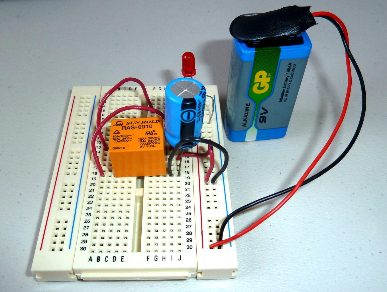
Like this:
If you connect a battery to the electromagnet of a relay, through its normally closed contact, you will get a relay that switches on and off really fast.
If you add a big capacitor (like 1000 µF) over the electromagnet, the electromagnet will stay on longer.
Then, if you replace the connection from the normally closed contact to the electromagnet with a resistor, you will increase the time it takes to charge the capacitor.
That means the relay will stay off for longer also.
Connect a light to the normally open contact, and you have a blinking light!
This is the basic principle on blinking a relay.

10 Simple Steps to Learn Electronics
Electronics is easy when you know what to focus on and what to ignore. Learn what "the basics" really is and how to learn it fast.
I explain this with images in my eBook “Getting Started With Electronics”:
https://www.build-electronic-circuits.com/products/ebook-2nd-edition
BUT…
One problem that might arise is:
If the resistor you added is too big compared to the resistance of the relay coil – you won’t get enough voltage on the coil to make it turn on.
That’s because the resistor and the coil make up a voltage divider.
Which I’ve written about here:
https://www.build-electronic-circuits.com/voltage-divider
So keep that in mind if you try to build it.
Keep on Soldering!
Oyvind
More Mail Archive Tutorials
10 Simple Steps to Learn Electronics
Electronics is easy when you know what to focus on and what to ignore. Learn what "the basics" really is and how to learn it fast.
l wish to benefit from your newsletter so as to learn how to build circuits and able to repair also. Am looking forward to hear from you! Thanks.