The CD4017 IC is a decade counter that counts to ten. It has 10 outputs that represent the numbers 0 to 9. The counter increases with one for every rising clock pulse. After the counter has reached 9, it starts again from 0 with the next clock pulse.
This is a great chip for making running LEDs! See a circuit example further down.
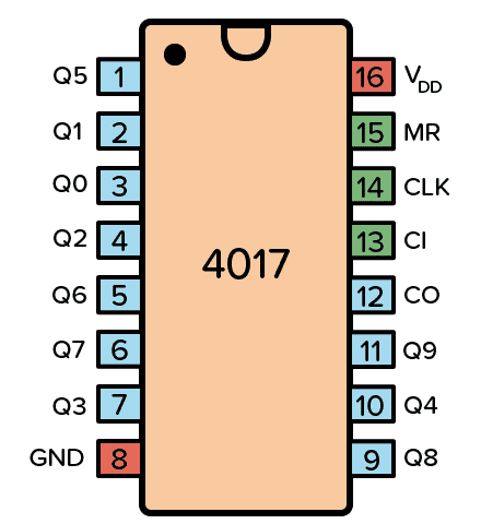
Pin Overview
| Pin Name | Pin # | Type | Description |
|---|---|---|---|
| VDD | 16 | Power | Supply Voltage (+3 to +15V) |
| GND | 8 | Power | Ground (0V) |
| Q0-Q9 | 1-7 and 9-11 | Output | Qx is high when the counter is x |
| CO | 12 | Output | Carry Out. Goes high after ten clock pulses |
| CI | 13 | Input | Clock Inhibit. Ignores clock inputs |
| CLK | 14 | Input | Clock Input. Increases the counter with one |
| MR | 15 | Input | Resets the counter to 0 |
What is a Decade Counter?
A decade counter counts to 10. You can remember it by thinking of a decade in years, which is ten years.
It’s very common that a counter will give you the output in binary form. But the output from the decade counter in the CD4017 is decoded, meaning that it will set one of the output pins (Q0 to Q9) high corresponding to the counter value. Ex: If Q3 is high, the counter value is 3.
The easiest way to create a decade counter is by connecting 10 D flip-flops in series to create a shift register. Then you connect the output of the last flip-flop back into the input of the first. And you connect the reset signal so that it sets the first flip-flop to one and the rest to zero on reset.
This is also known as a ring counter. Below you can see an example of a 4-bit ring counter:

The counter circuit in the CD4017 however, is not a standard ring counter. Instead, it uses a technique called a Johnson counter that makes it possible to achieve the same with only 5 flip-flops plus some logic gates.
Typical applications for the CD4017 include LED chasers, alarms, frequency dividers, or even a music sequencer.

10 Simple Steps to Learn Electronics
Electronics is easy when you know what to focus on and what to ignore. Learn what "the basics" really is and how to learn it fast.
How To Use The CD4017
First of all, you need a power supply voltage of 3 to 15V. Most versions of the chip support up to 18V. But for instance, the HEF4017 recommends only up to 15V.
Connect the VDD pin to the positive terminal and the GND pin to the negative terminal.
The Clock (CLK) pin increases the counter with one every time the pin goes from low to high. And as the count increases, the output pins (Q0-Q9) get high one by one. After the 10th input pulse, the counter resets and starts from 0 again. Change this pin from low to high to increase the counter.
The output pins Q0 to Q9 goes high one by one as the counter increases. Connect each to a resistor and LED if you want to see pins change state.
The Clock Inhibit (CI) pin disables the counter so that any clock pulse on the CLK pin is ignored. Set this pin to low to enable the counter.
The Carry-out (CO) pin goes from low to high when the counter reaches 10 and resets back to 0. It stays high for 5 clock pulses, then goes low again. Connect this pin to the clock input of another decade counter if you want to count higher than 10.
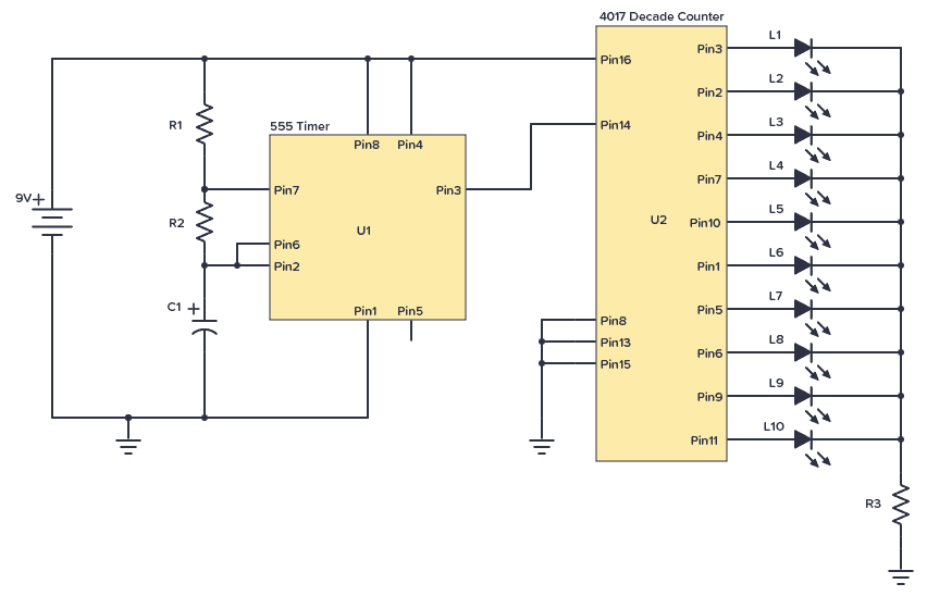
CD4017 Example Circuit – Running LEDs
One of the most popular hobbyist projects to build with this chip is the running LEDs circuit. It works like this:
A 555 Timer is set up in astable mode, which makes it into an oscillator circuit that creates a clock signal. This clock signal goes into the clock input of the IC 4017. Every time the clock input goes high, the counter in the 4017 increases, which makes the next output HIGH. LEDs are connected to each of the outputs and therefore appear to be “running” along a line.
Here’s the circuit diagram:
Component List
| Part | Value | Note |
|---|---|---|
| R1, R2, R3 | 10 kΩ | Three standard resistors |
| C1 | 4.7 μF | Polarized capacitor |
| L1 to L10 | LED | Standard light-emitting diode |
| U1 | NE555 | 555 Timer IC |
| U2 | CD4017B | 4017 Decade Counter |
Note: Some versions of the 555 IC require a 0.01µF capacitor between pin 5 and ground/minus.
The LEDs blink in sequence from the first to last and then starts from the first again. You can use this technique, for example, to create blinking Christmas lights.
After reaching Q9, the 4017 will restart the count and restart from Q0. If you want to limit the number of LEDs, all you have to do is connect the corresponding next output bit to the MR pin.
For example, if you have only 5 LEDs, connect the Q6 to the MR pin. When the count reaches the 6th bit, it sets the MR pin and resets the operation.
With some small modifications to the circuit above, you can build the knight rider LED bar:
How To Set the “Running” Speed
The number of times the output from the 555 Timer goes HIGH per second is the frequency and is given in Hertz (Hz). For example, 10 Hz means ten times per second. And that means the LED moves 10 positions per second.
The resistors R1 and R2, and the capacitor C1 decide the frequency according to this formula:
Frequency: 1.44 / ((R1 + R2 + R2) * C1)
Note: R1 should never be less than 1 kΩ as it might damage the chip when Pin 7 (Discharge) is connected to ground.
If you want to try different values, you can use this 555 Timer calculator to help you.
Alternatives and Equivalents for CD4017
You likely find the 4017 IC marked as CD4017, NTE4017, MC14017, HCF4017, TC4017, or HEF4017. Usually with a few extra characters at the end (Ex: CD4017BE).
This has to do with the manufacturer of the chip and the technology used. But the functionality and the pins are the same.
If your local electronics store doesn’t have any of these chips, check out my list of online stores for other places to buy from.
The CD4017 is a very common IC, so you should be able to find it in one of the online stores. But as an alternative, it’s possible to use a BCD counter such as the CD4510. Then connect the output of it into a CD4028.
4017 Datasheet
Download the PDF datasheet for the IC 4017 here:
CD4017BE (Texas Instruments)
HEF4017B (Nexperia)
10 Simple Steps to Learn Electronics
Electronics is easy when you know what to focus on and what to ignore. Learn what "the basics" really is and how to learn it fast.

An excellent page!
It helps me a lot to handle the 4017.
One question:
What do I do if I want the LEDs to run just once and then get the 4017 back to a “ready to start again” status triggered by a switch or a light sensor?
I tried a time value with a NE555 but that seems to confuse the 4017.
Best wishes and stay healthy
Thomas
Thanks Thomas!
The 4017 goes to the next light every time the CLK pin goes from low to high – unless the CI pin (pin 13) is set to HIGH.
So if you connect the last output (pin 11) to pin 13, the 4017 will ignore any clock pulses after the 10th LED is lit.
To restart the circuit, use the Reset pin with whatever you want to use as a trigger.
I am wondering how I can use my CD4017 to make a binary counter.
Any directions would be much appreciated.
You would need to convert the output into binary somehow. With logic gates I think it would become a mess. Not sure if a chip exists for that, but maybe.
But binary counter chips exist, such as the CD4040
Peter
4520 is a 4 bit binary counter that counts from 0000 to 1111 (0 to 15) 16 bits. 4518 is a BCD counter that counts from 0000 to 1001 (0 to 9) BCD stands for Binary Coded Decimal so kinda like the 4017 Decade counter but in binary form.
Hope that helps
I am trying to make the 4017 to count 1-2-3 and repeat 1-2-3 a gene and a gene.
I don’t know what I’m doing wrong. I am getting 1-2–3 with a mise and then 3, and then it repeats.
My first suggestion would be to check if you are using the correct output pins. Maybe you are using 1, 2, and 4?
Hello. I’d like to run a sequence of 4 LED lights instead of 10. Is there a CD4014 like IC that only supports 4 or 5 outputs? Run the sequence of 4 or 5 lights then restart again. Thanks!
Hi Michael, you can do this with the CD4017. Let’s say you want 5 outputs. Then you take the 6th output (Q5/pin 1) and connect directly to the reset pin (pin 15). The reset pin should not connect to anything else.
Thank you very much sir, it’s very useful to me sir. Because Iam beginner of electronics circuit leaner. Thanks again sir.
I am wondering how I can use my CD4017 to how to connect to yhe monitor and use remote contral
Hi admin I was wondering if I or how I could use this circuit to switch on and stay on several led lights one after the other and hopefully when switched off they would also go off one by one in reverse order ???
Trying to make my driveway
lights come on and off like runway lights as you drive in
Many thanks and keep up the great web page
Hi Tony,
The first idea that comes to mind is to use a toggle flip flop on each output from the 4017. The first round that the 4017 does will turn the lights on, one-by-one. The second round will turn them off, one-by-one.
Here’s more on the T flip flop: https://www.build-electronic-circuits.com/t-flip-flop/
merci beaicoup.
si je comprend bien, quand il faut régler la minuterie à 2 heure il faut que le reseau RC de NE555 soit capable de faire une sortie haut à la broche 3 du ne 555 a chaque 12 minutes ?
Is there a possibility to use a rotary encoder with 2-bit quadrature code (Bourns PEC11L-4115K-N0020) to increase AND to decrease the output from 4017?
I’m designing a multi cable tester (All-in-one :D) which I’m going to use for testing 2 to 20-pin cables. The idea of this would be to be easily move between the pins to see that how they connect, so that it would be easy to go back.
Any ideas if this isn’t working?
Hi Mike, the 4017 can only count upwards, so you can’t decrease the counter.
How can I make the leds fade or strobe? Thanks
Hi James, you can place a capacitor in series or in parallel with each LED.
Thanks for this lesson. My 555 pin 3 has a freq of 1 hz. When I turn the circuit on, the LEDs flash one by one during the 1 hz cycle. I thought each LED would flash for 1 hz, then go to the next LED. I connected 4017 pin 15 and 13 to pins 7 and 8. Is this correct? How can I control the cycle of each LED, or is this even possible? I’m new to working with these types of chips. Thks.
Hi Gary,
Pin 7 is an output and shouldn’t be connected to pins 15, 13, and 8. Do you want each LED to turn on for 500ms, then turn off for 500ms, before the next LED turns on for 500ms and so on? Then you just need to connect your LEDs to every other output.
So connect LEDs to Q0, Q2, Q4, and Q6, and leave the rest unconnected.
Hello.
An excellent page!
It helps me a lot to handle the 4017.
One question:
What do I do if I want to run a sequence of 17 LED lights with the CD4017.
Best wishes and stay healthy
mehrdad
You’d need two 4017 chips and make sure the output number 18 resets the chips.
Thanks for this helpful site. Here is my long-winded query:
I have a crystal oscillator circuit outputting 1hz (a kit from eBay). Clocking four 4017s in a chain, I want to output a pulse exactly every hour. This is to drive a Westminster chimes module. The first two 4017s will count to 10 seconds, the second to 9, and the fourth to 4. That will be 10 x 10
x 9 x 4 = 3,600 seconds – 1 hour! I know you use the carry pin on the first two but I’m not sure how you connect the third and fourth. Then how do I reset the lot to start again?
Hi Bill, interesting project!
You can use the 9th and the 4th output from the last two instead of the carry out. Since you want them to start from 0 again after reaching 9 or 4, you’ll have to also connect that output to their own reset pins. I made an example circuit here: https://circuitcanvas.com/p/a46vmxnthisji6v16gx
Best, Oyvind
what if i want to connect a seven segment display instead of the LED’s how do i bread board that?
Every time I switch on the circuit it does not start at 1, then after a while it get into sequence.
How can mI ensure it always starts at 1 when I switch the power on.
Are you sure you are looking at Q0 (pin 3)? It should always start at the beginning.
What if i connect the clock pin to a switch to trigger the IC for the first time then connect the output Q1 via diode for example to the clock pin and the output Q2 to the reset pin does the high ouptut oscillate between the Q0 and Q1.
The signal from Q1 will go high almost at the same time as the clock signal, so you won’t get two distinct clock pulses. If you add some kind of delay to the signal from Q1 before it reaches the clock, you might be able to get it to oscillate like that.
Buen día me gustaría controlar 10 módulos led con potencia de consumo de 1w cada uno en color ámbar. Conlas salidas del 4017; pero no puede, ya k sus salidas son de muy baja corriente.
La fuente de alimentación son 4 baterías conectadas en paralelo de 12 V y 10 A .
Que puedo hacer, o como conecto los transistores bc547 para brindar la potencia necesaria y así poder utilizar el circuito del 4017 y controlar esos módulos en secuencia?
Nota. Las luces se instalarian en camión de carga (trailer) .
Gracias
Will you help me find or tell me where I can go, even if I have to pay for it, a Astable circuit that has a 555 timer creating a pulse to a CD4060 binary clock counter, then to CD4017 decoders then to 7-segment displays? This circuit schematic needs to be complete as I’m not a engineer or electronics guy. I’ve soldered a few circuit boards but I’m not pro, so pin selections need to be given and all points to ground and positives need to be clearly marked. Can you help me?
This circuit has a duty time of ON for 15 seconds and OFF for 900 seconds
Created the whole circuit and LEDs did not light up. Finally put an NPN transistor on all the LEDs and it lit up. Seems like the current from the output pins is not enough to drive the LEDs by themselves.