A Solid-state relay (SSR) is an electronic switch without moving parts that use semiconductor technology to turn things on and off. In this guide, you’ll learn how they work, what they are used for, and how you can apply them in your circuits.
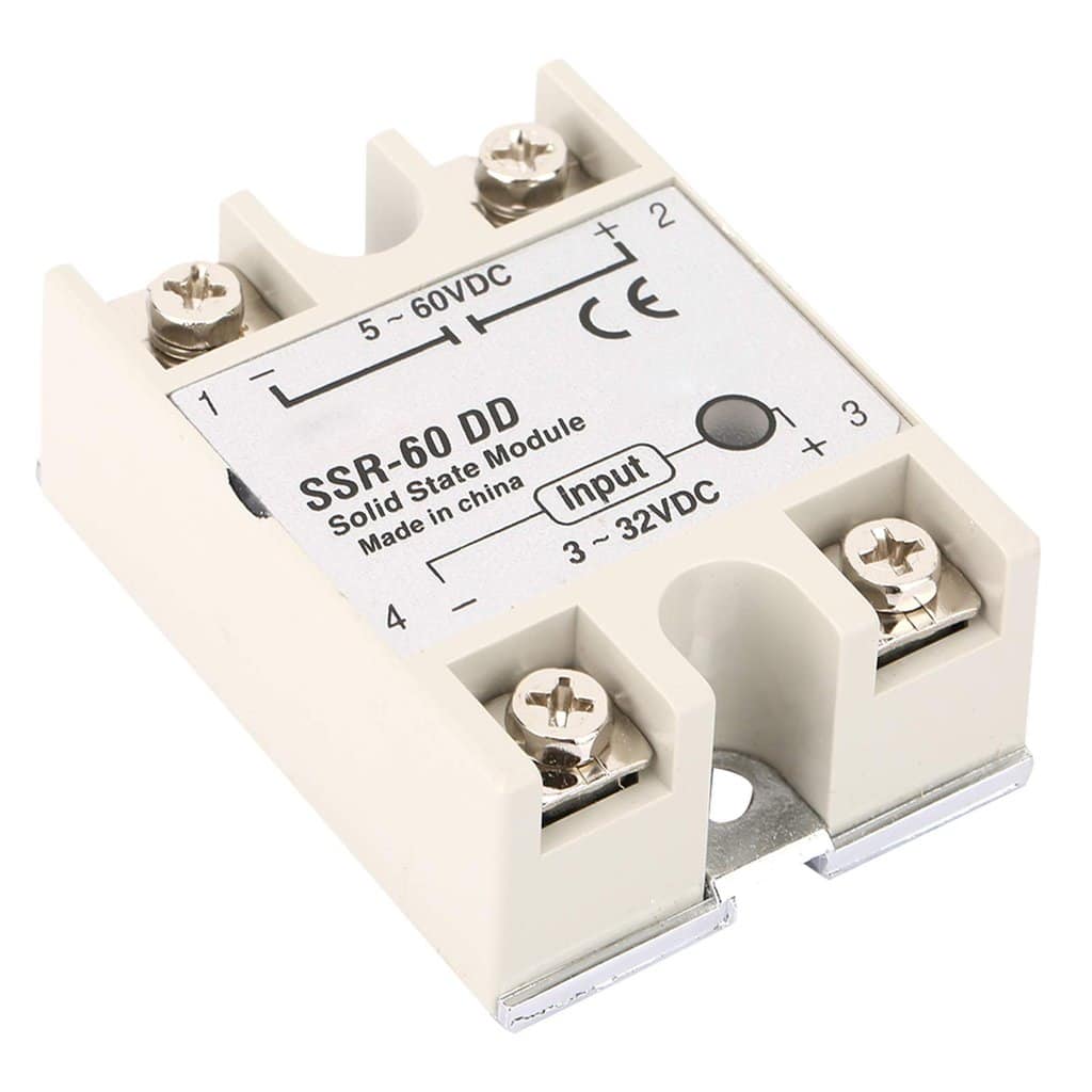
Relays are very important in electronics because you can use them to turn on/off high-power devices, for example, you can control air conditioners, heaters, or even entire lighting systems with just a small signal DC input.
There are two main types of relays: electromechanical relays and solid-state relays (SSR).
Electromechanical relays are built with physical switches and electromagnets. While solid-state relays are built from solid state components, such as transistors, to perform the same function without any moving parts.
How does a Solid-State Relay Work?
To understand how SSRs work, take a look at following diagram that shows what an SSR looks like on the inside:
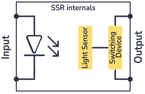
The SSR has three main components:
- A Light-Emitting Diode (LED)
- A light sensor (ex a photodiode)
- A switching device (ex a transistor)
In some cases, the switching device is also photosensitive (ex a phototransistor), so that there’s no need for an additional light sensor.
When a control signal (e.g., 5V DC) is applied to the input terminals of the SSR, it powers the LED. When the LED turns on, the light is detected by the light sensor on the output side and turns on the switching device so that current can flow.

Get Our Basic Electronic Components Guide
Learn how the basic electronic components work so that circuit diagrams will start making sense to you.
This isolates (electrically) the low-voltage control side from the high-voltage load side. Such a setup is called an optocoupler.
The light sensor activates the trigger circuit, turning on the switching device in the output circuit, thereby connecting the power source to the load. The switching device remains on as long as the control signal is present, keeping the load powered. When the control signal is removed, the LED turns off, the light sensor stops detecting light, the trigger circuit deactivates the switching device, and the load is disconnected from the power source.
The switching device can be a MOSFET transistor, an IGBT, a Triac, or an SCR, depending on the type of SSR you are working with.
Types of Solid State Relays
The classification of SSRs depends on the type of input signal you can apply and the type of load you can control. For example, SSR types include:
- DC-to-AC
- AC-to-AC
- DC-to-DC
- DC and AC output
DC-to-DC SSR
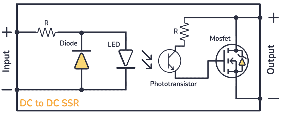
A DC-to-DC SSR would allow you to use a low-voltage DC signal to control another DC device. These relays typically use switching devices like MOSFETs or IGBTs transistors at the output to control the flow of current in the DC circuit. Take a look at its circuit:
DC-to-AC SSR
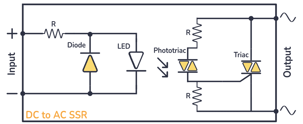
With this kind of SSR you can use a low-voltage DC signal to control a device that runs on AC power. A DC-to-AC SSR relay typically has a Triac or SCR (Silicon Controlled Rectifier) at the output. These components are used to switch the AC load on or off when they receive the signal from the control circuit. You can check its internal diagram below:
AC-to-AC SSR
The AC-to-AC SSR, along with the components previously mentioned, such as the led, the light sensor and the Triac or SCR at the output, there’s a rectifier bridge in the input circuit. This rectifier bridge is responsible for converting the AC control signal into a form that can be used to activate the relay and control the AC load.
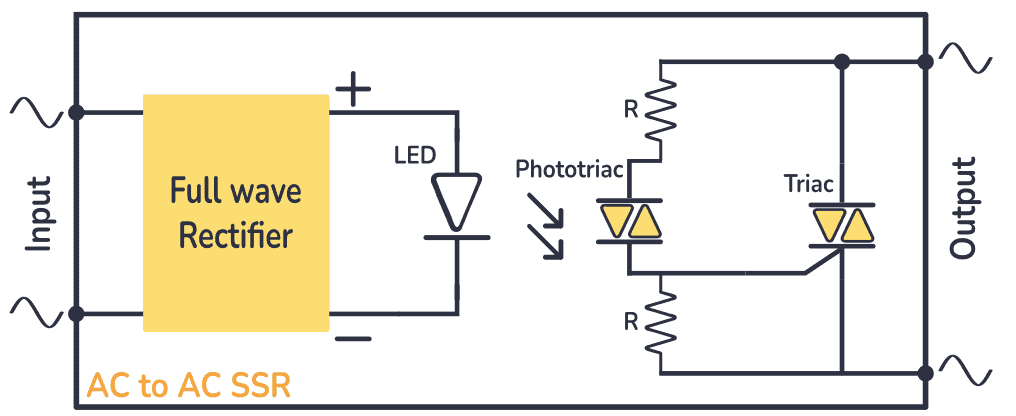
DC and AC Output SSR
These relays are useful when you need to control both DC and AC devices or circuits using the same control signal. They typically incorporate different types of switching components for DC and AC output, such as MOSFETs or IGBTs for DC and Triacs or SCRs for AC.
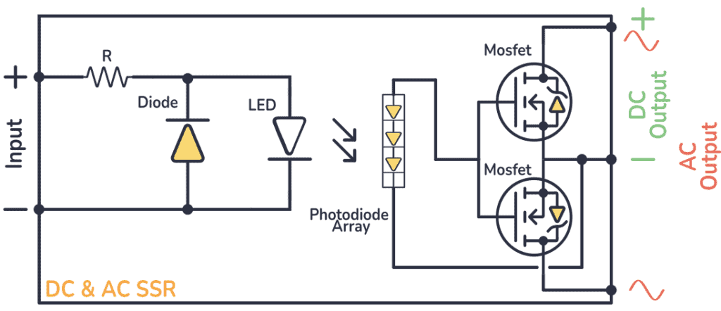
Don’t overwheel with the circuit above, what you really should focus on is that there are separate outputs according to what kind of load you are going to control.
How To Use a Solid-State Relay?
To turn the SSR input on and off, you need to control the input side with a low-power signal, such as the output from a microcontroller or another digital device. For example, let’s control an AC lamp using an Arduino and DC-to-AC SSR.
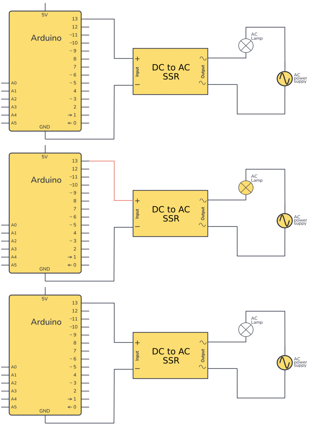
- Arduino Pin to SSR Input (+): Connect a digital output pin from the Arduino to the positive input terminal of the SSR.
- Arduino GND to SSR Input (-): Connect the ground (GND) pin of the Arduino to the negative input terminal of the SSR.
- SSR Output Terminals: Connect one SSR output terminal to one side of the AC lamp and the other SSR output terminal to the AC power supply.
- AC Lamp: Connect the other side of the AC lamp to the remaining terminal of the AC power supply.
Questions ?
Do you have any questions about Solid State Relays or any feedback you want to share? Let me know in the comments below!
More Electronic Components Tutorials

Get Our Basic Electronic Components Guide
Learn how the basic electronic components work so that circuit diagrams will start making sense to you.
