In this guide, you’ll learn exactly how a Zener diode works and how to use it in circuits.
Did you know that some of the common things you can build with Zener diodes include simple power supplies and guitar pedals?
Sounds interesting? Let’s jump in!
What Is a Zener Diode?
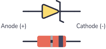
A Zener diode is a type of diode that is often used for voltage regulators and shaping waveforms.
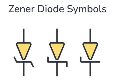
Its symbol is an arrow pointing towards a crooked line. There are actually three different ways you can draw the Zener diode symbol in schematics:
While a normal diode only allows current to flow through a circuit when it is forward-biased (current going from anode to cathode), the Zener diode also works when it is reverse-biased (current going in the opposite direction).
With standard diodes, if you place it in reverse, no current flows.
At least, so it appears. But actually, if you apply enough voltage in reverse, current will start to flow.

10 Simple Steps to Learn Electronics
Electronics is easy when you know what to focus on and what to ignore. Learn what "the basics" really is and how to learn it fast.
This voltage is called the breakdown voltage of the diode.
For example, the rectifier diode 1N4001 has a breakdown voltage of 50V.
The Zener diode is basically the same as the standard PN junction diode. However, it is specially designed to work in reverse bias with a low and specified reverse breakdown voltage.
So, why is that interesting?
Because you’re not limited to the standard forward voltage of 0.7V. You can design the breakdown voltage to be for example 3.3V or 12V – or many other voltages. The manufacturers call this Zener Voltage (Vz).
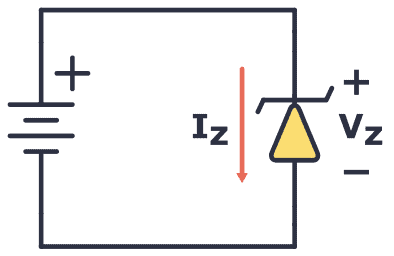
This means a Zener diode can act as a voltage regulator because it keeps the breakdown voltage at a nearly constant value across its terminals.
How To Make A Zener Diode Voltage Regulator
Making a voltage regulator is easy with the Zener: Just add a resistor!
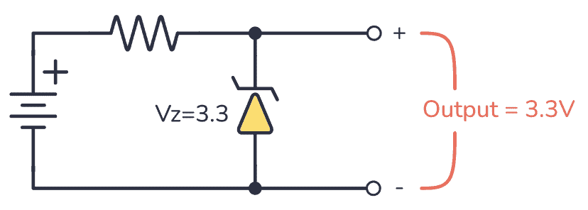
Here’s how it works:
When a voltage (must be higher than the Zener voltage) is applied across the resistor and Zener diode, the diode starts conducting in reverse and keeps the voltage drop across it at a constant value of 3.3V.
The rest of the voltage drops across the resistor. This means the resistor acts as a current-limiting resistor so that you can easily calculate the current by using Ohm’s law.
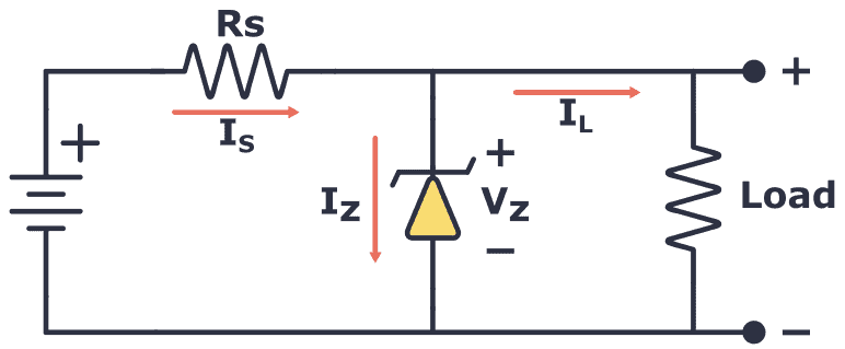
The resistor (RS) limits the maximum current that can flow through the circuit. If there is no load connected to the circuit all the current flows through the Zener diode, causing it to dissipate its maximum power.
A smaller value of resistor RS gives you a higher maximum current. But at the same time, you have to make sure that you don’t exceed the maximum power rating of the Zener. Therefore, it’s important to choose the right value of series resistance.
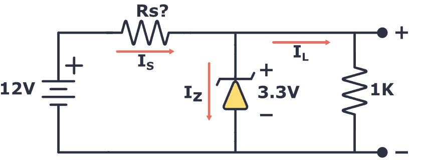
Example: Choosing a resistor for a 12V to 3.3V voltage regulator
In this example, you’re going to use a Zener diode that can handle up to 2W of power. What’s a suitable value for the resistor (RS)?
First, you need to find the maximum current that can flow through the Zener diode:

That means that the minimum value of the resistor is:

So a value of 14.5 Ω is the absolute minimum. But you can use higher resistances of course.
Next, you need to check how much current your load needs. The load resistor is 1 kΩ, so its current is calculated as follows:

That’s much lower than the 0.6A you’d get from the 14.5 Ω resistor, so no problem here.
If you want to use a higher resistor value, just use the following formula with your chosen resistor value and make sure that it’s above the current you need for your load:

For example, if you want to use a 100 Ω resistor, this would give you a maximum current of:

Still, high above the needed 0.0033A for the load, so you’re good to go.
That said, Zener diodes have their disadvantages. Check out this article about why Zener diodes make lousy voltage generators.
Wave-Shaping With the Zener
In the previous example, you saw how the Zener works with DC power. However, what happens when it’s used with AC power? How would it react to a constantly changing signal such as an audio signal?
Check out the following circuit:
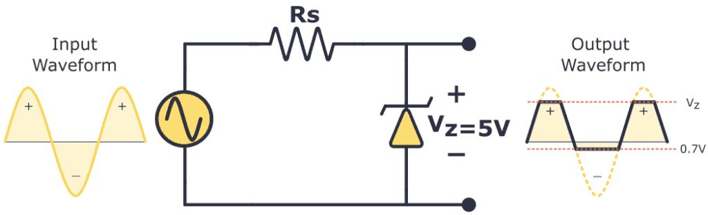
In the above diagram, the Zener diode has a VZ of 5V, so if the waveform exceeds this limit, the diode will “clip off” the excess voltage from the input, resulting in a waveform with a flat top maintaining a constant output of 5V.
When forward-biased, the Zener diode behaves like a regular diode. So when the waveform reaches negative values below 0.7V, the Zener acts like a typical rectifier diode, resulting in output clipping at -0.7V.
Zener Diode Example: Distortion Guitar Pedal
Diode clipping and clamping circuits can shape a waveform to produce an output waveform with a different shape. A clipper circuit clips off the positive or negative part of an AC signal, which is why they are commonly used as waveform shaping circuits.
When you cut off the top of an audio signal, it sounds distorted. This is exactly what you want in a distortion guitar pedal!
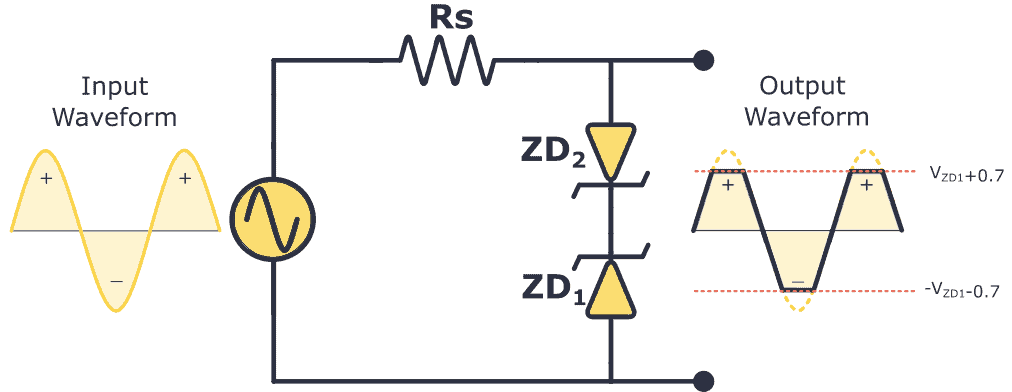
But the output signal of an electric guitar isn’t high enough to be clipped. So in order to clip it, you must amplify it first. Here’s a basic guitar distortion pedal circuit that uses Zener diodes to distort the sound:
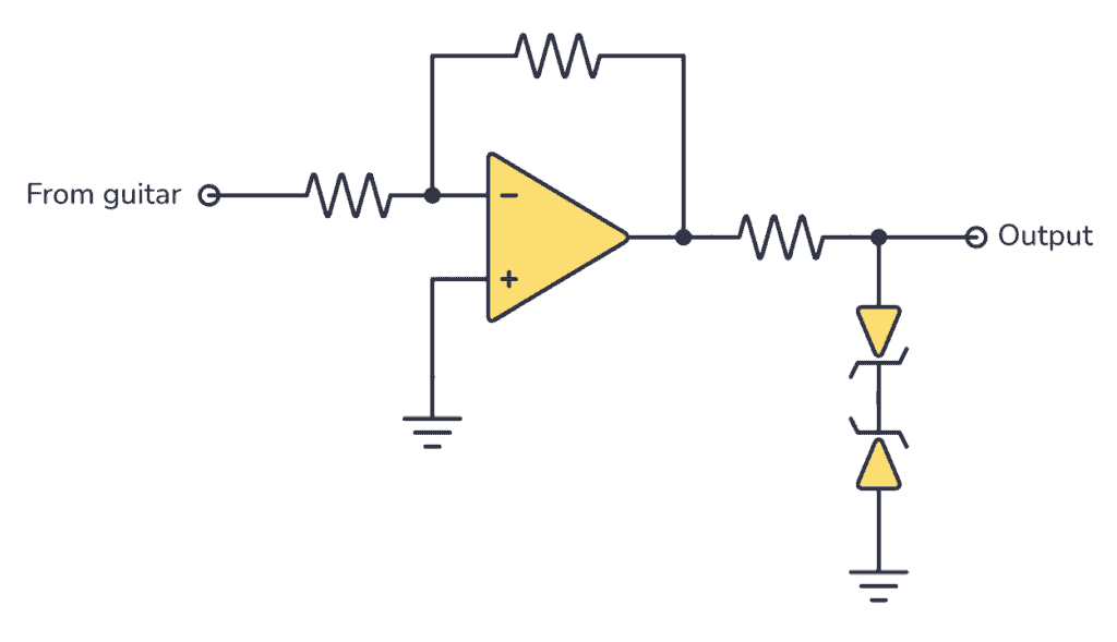
So, if you build the circuit above the output waveform will be clipped at the VZ voltage plus 0.7V, which is the forward voltage drop of the other diode.
Zener Diode Characteristics (The I-V Graph)
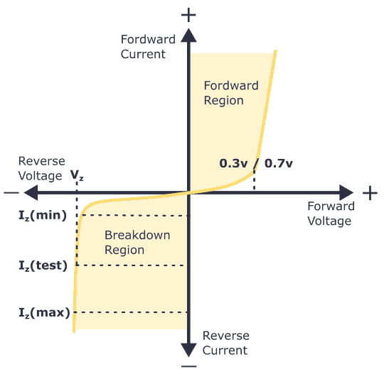
The I-V characteristics curve of a Zener diode is shown in the image above. By studying this graph, it becomes clear why Zener diodes are employed in reverse bias.
By observing the behavior of a Zener diode, you can notice that as the reverse voltage rises, the reverse current also increases gradually until it hits the Zener knee current, IZ (min). At this point, the breakdown effect starts, and the Zener impedance (ZZ), which is the internal resistance of the diode, begins to rapidly decrease as the reverse current increases.
In general, the breakdown voltage of the Zener (VZ) is fairly constant, although it increases slightly with increasing Zener current (IZ). VZ is commonly set at a value of the Zener current known as the IZ (min).
A Zener diode’s ability to maintain almost constant voltage in its breakdown region makes it suitable for regulating voltage even in the simplest voltage regulator applications.
A voltage regulator’s main role is to deliver a steady output voltage to a load connected in parallel. This is even when the supply voltage has ripples or the load current varies. Zener diodes can maintain a constant voltage output as long as their reverse breakdown region holding current does not drop below IZ (min).
Common Zener Diode Voltages
Here you have a table with the most common Zener voltages in diodes of 0.3 W and 1.3 W.
| 0.3W BZX55 zener diode | |||||||
| 2.4V | 2.7V | 3.0V | 3.3V | 3.6V | 3.9V | 4.3V | 4.7V |
| 5.1V | 5.6V | 6.2V | 6.8V | 7.5V | 8.2V | 9.1V | 10V |
| 11V | 12V | 13V | 15V | 16V | 18V | 20V | 22V |
| 24V | 27V | 30V | 33V | 36V | 39V | 43V | 47V |
| 1.3W BZX85 zener diode | |||||||
| .3V | 3.6V | 3.9V | 4.3V | 4.7V | 5.1V | 5.6 | 6.2V |
| 6.8V | 7.5V | 8.2V | 9.1V | 10V | 11V | 12V | 13V |
| 15V | 16V | 18V | 20V | 22V | 24V | 27V | 30V |
| 33V | 36V | 39V | 43V | 47V | 51V | 56V | 62V |
More Diodes Tutorials

Get Our Basic Electronic Components Guide
Learn how the basic electronic components work so that circuit diagrams will start making sense to you.
Can I get the regulated DC output power of 300ma or 500ma using the Zener diode ??
Are you talking about building a constant current source? Then no. The zener diode is for getting a fixed voltage, not current.
Hi, Ovind!
How current acts in the diagram of “Zener Diode Example: Distortion Guitar Pedal” section?
If I have a 3 phase stator that is outputting 25 – 250 volts ac across any 2 phases and I need a constant 13-15v DC would a bridge rectifier work using zenner to regulate it