When you start learning about circuits, you’re bound to ask “what is ground?” at one point or another. Are you actually suppose to connect your circuit into the ground??
First of all: grounding in electronics is different from the earth connection in wall outlets (although they sometimes are connected).
Grounding in electronics
I got an email from a reader a little while back:
«The ground symbol keeps appearing at different points in a circuit and I could not understand why a particular place was chosen for grounding. What is ground?»
Grounding something simply means connecting it to ground.
And in electronics, ground is just a name we give to a certain point in the circuit.
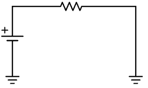
For example, in a circuit with one battery (with a positive and a negative terminal), we usually refer to the negative terminal as ground.
And to simplify drawing the circuit, we use a symbol.

Get Our Basic Electronic Components Guide
Learn how the basic electronic components work so that circuit diagrams will start making sense to you.

So instead of drawing lines to all the places that should be connected to minus, you instead place the ground symbol there. This makes the circuit diagram much cleaner when there are a lot of connections to minus.
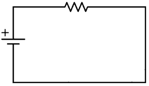
Flow of Current When the Ground Symbol is Shown
To see how the current flows in a circuit diagram with ground symbols, just connect all the points that have ground symbols. That is what you do when you build the circuit.
Circuits With Positive, Negative and Ground Connections
In some schematic diagrams, you’ll find a connection to a positive terminal, a negative terminal, and a ground terminal.
This is common in for example amplifier circuits:
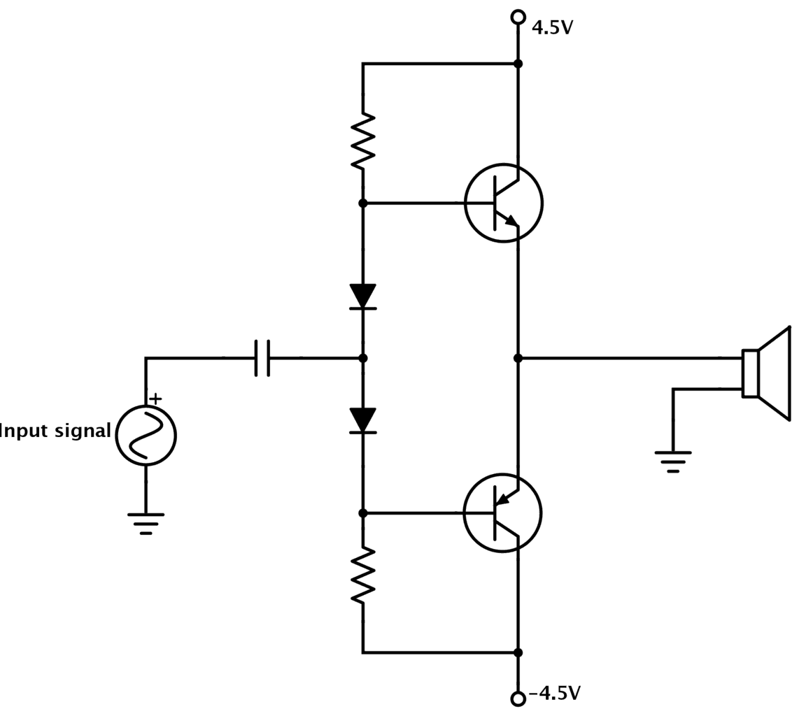
So, how does this work?
In this scenario, the ground is the middle-point between the positive and the negative terminal. You can create these three voltage points for example by connecting two power sources in series:
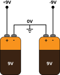
Since the ground terminal is in the middle between +9V and -9V, it’s normal to call it zero volts (0V).
Click here to learn what negative voltage is.
What is the Earth Ground in wall outlets?
Sometimes though, grounding refers to an actual connection to the earth. That is the case when talking about the wiring of the wall outlets in your house. In this case, the earth ground connection is an actual connection to the ground outside your house.
This connection is for safety and is often wired to the chassis of an appliance. The idea is that if a problem arises so that a live wire comes in contact with the chassis, the current is guided to the earth instead of through your body if you touch the chassis.
In some cases, for example in audio amplifiers, it’s common that the signal ground is also connected to the chassis, and thereby to the earth too.
Questions? Let me hear ’em in the comments below!
More Schematic Diagram Tutorials

10 Simple Steps to Learn Electronics
Electronics is easy when you know what to focus on and what to ignore. Learn what "the basics" really is and how to learn it fast.
How to ground?
If you connect something to ground, it’s grounded.
Your ground symbol is wrong. You used electric ground in your schematic.
It’s either horizontal line, or down arrow.
From a bit of Googling, looks like you might be right. Do you have a trustworthy reference that you can link to? It would be good to know for sure, instead of “someone on the internet said that it’s so”
what is the benefits that we got. with connect grounding in our electrical installations?
it means that the grounded part have same potenital as that point , like battery negative terminal
:)
If we connect positive, negative and ground terminals,what will be the function of ground there if the potential is 0?
I don’t understand your question.
I like this website because it explains
What happens if we give improper grounding?
Then your circuit won’t work properly.
thanks it helps soooooo much
You guys are really d o w n to e a r t h !
Does it mean that all the grounds are connected together
Yes. But in some cases you have more than one ground. Ex: analog ground and digital ground. In this case all analog ground are connected together, and all digital ground are connected together.
I need a short video on grounding
So in the case of above amplifier circuit, can we connect together both negative and ground terminal.
Do we need to connect the ground with the common earth of the house and building
Or can we leave it separate without connecting anywhere.
Your first question: “…can we connect together both negative and ground terminal.”
The answer: NO! Not under any circumstance would you ever want to do this. It’s the same thing as if you said, “…can we connect together both positive and ground terminal.” The answer is obviously NO!
Your second question: “Do we need to connect the ground with the common earth of the house and building”.
The answer: It depends on the circuit. In other words, it won’t hurt anything if you do it but it depends on whether you want your circuit to have an earth (house or building) ground or if you don’t want that. For example, most desktop digital multimeters that are plugged into an outlet do not have their circuits grounded to earth ground. However, if you check an older Techtronics oscilloscope, they DO have their internal circuits grounded to earth ground. Unfortunately though, this makes some readings difficult to measure but there is a way around this problem.
So, as I said, it depends on your circuit and what you want to do with it.
To first question – The answer is NO!
Yeah. But why?
To be honest this article makes more problems with understanding than without it. As I see by comments the article should be rewritten. Can you explain what do you mean by “grounding”?
Please add some pictures with real applications. The paper will accept anything. The pictures of practical examples would be very useful.
Hi Matthias,
Thanks for your feedback.
“Grounding” something simply means connecting it to ground.
I’ve updated the article. Let me know if you have any other questions.
Best,
Oyvind
What happens when I touch an element/trace that is connected to ground (negative terminal) and a part of circuitry that is connected to positive terminal? :)
No explanation of it at all.
What about noise cancellation. In other words: Is ground, or grounding really connecting to negative terminal, or is it doing something else as well?
Why bodywork in old cars was used for grounding?
Hello sir..
I stucked in your explanation..
I.e. how the free electrons flow in circuit..
Condition 1…
In positive to negative that is closed circuits.. The free electrons of conductor will moves continuously.. Through the circuit
That you explain electrons move from the conductor not from the battery… (it’s uses only for force)
Condition 2…
For positive to grounding..
The free electrons not back in the circuits..
So my question is..
Is that load run until the electrons will end from the conductor.. (In grounding) Before the battery dead..
Or battery will also have free electrons..
Or I have confused a lot..
Please help..
how can i know which electronic component i have to ground?
this electronic component usually has either “GND” on it or a negative sign. It is usually next to the power or control pin.
Electricity newbie here! In the article it states: “The idea is that if a problem arises so that a live wire comes in contact with the chassis, the current is guided to the earth instead of through your body if you touch the chassis.”
Why is this the case? I haven’t been able to find a good explaination as to why connecting something to the earth would redirect the current.
Thanks in advance!
I would love someone to answer this question! I wonder the same thing. More specifically, I was once told that Earth has infinite resistance. It’s basically dirt and rocks, and some minerals. Why would the electricity that hits the chassis go into the Earth instead of my body? Earth seems like it has far higher resistance than my body. I just don’t understand the grounding concept. Thanks!
The answer is nowhere to be found. I think I will look in books dedicated to electricity.
People who write, or record electronics lessons ommit this thing, leaving rookies with no explanation: why it should be done this way, how it works, or why it works the way it works, etc.
Hi,
Happy New year:) I’m very new to electronics,
Just read this, https://www.techopedia.com/definition/11566/ground-gnd
” What does Ground (GND) mean?
Ground, in the context of electronics, is the reference point for all signals or a common path in an electrical circuit where all of the voltages can be measured from. This is also called the common drain since the voltage measurement along it is zero.
Ground means something entirely different for electronic circuits. It is considered as the common reference point to measure voltage against any point of the circuit and is considered to have zero voltage. It is also the common connection that all electrical components must connect to in one way or another in order to complete the circuit. ”
You say GND is the connection to the – V supply ie 15-V. How can I measure voltage if is already -15V? I’m confused, could you clarify make clearer please?
If you have a dual supply with +15V, 0V, and -15V, then GND would be 0V not -15V.
But if you have for example a battery with plus and minus, then ground would usually be the minus. Note that the minus connection of a 9V battery is NOT -9V, it’s 0V.
Sir Please reply ,,
I have stucked on it…
That I asked on December 3
That I asked on December 3rd
1. What is a dual suppply? Two batteries? If no, than why picture shows two batteries?
2. If negative terminal on battery is 0 not -9V, then where is -9V anyway? Is it only showned on schematics of devices that run on dual supplies?
I already asked on December 3rd
I have a remote control the power terminals state gnd an 12 + which I understand gnd is the same as neg- on a battery is this correct !? Thank you
Yes, that’s correct.
For me, this is becoming a very uncomfortable topic. For many years I’ve heard smart people use the term “ground” indiscriminately, and now certain people are getting into trouble and possibly someone will be hurt.
I understand how drawing a ground symbol is convenient, and using the word ground is just as easy. But I now have a case where a standalone 300V battery is used in a solar system, and the AC output of the inverter connects to the house wiring. Necessarily this involves a 220V split phase transformer with the center tap is grounded neutral, that is, earth grounded. Up until now, the designer has been calling the negative pole of the battery “ground” when in fact it was unreferenced, or floating. As a result of connecting the system to the house, the positive pole of the battery is now +150VDC and the negative -150VDC, when measured with respect to house ground. As a result of ignoring the real world earthing, they blew the inverter out. A far better term to use is “common” or “return”. Or simply call it what it is, the negative battery pole.
Then National Electric Code has had specific rules about grounding and for a few decades now, with an earthed connection required for ground. It’s time for people to wake up, do some critical thinking, and get their act together.
For printed circuit boards using return planes, the term “ground” is generally defined to mean the 0V reference potential of the return plane. Because the term “ground” is sufficiently ambiguous depending on the context, when drawing schematics I stopped using the triangular “ground” style symbols and instead define a 0V global power net to represent the reference potential of PCBs.
I now reserve the term “Ground” to mean “leading to earth or connected to earth”. This removes the ambiguity, and you can still tie 0V to “Ground” at a terminal connector of a PCB.
The Neutral conductor of AC house wiring is tied to earth/ground at a bus bar in the breaker box. A properly wired outlet should have no voltage between Neutral and the Ground/Earth pin of the outlet under no load conditions. When current is flowing in the neutral wire due to a load, a voltage may be present due to resistance of the Neutral wire. The ground wire should remain at earth potential as it is not intended to carry load current.
“Chassis” is another term that gets mixed in here, and generally means the metal box or metal frame of an electrical product. As mentioned in the article, metal chassis are usually connected to ground so that if a loose live/hot wire touches the chassis, the chassis potential remains at a safe potential, thereby reducing risk of electrocution, and also provides a return path so that the circuit breaker on the live wire trips and deactivates the circuit.
This is approaching what I am trying to understand about reading guitar amplifier circuit diagrams. I don’t understand why some areas of the circuit drawing show the “Ground” symbol, and others do not. I am looking at resistors, capacitors, pre-amp dual triode tubes like 12AX7’s, and power tubes like 6L6, 6v6, or EL84. At not time in the very detailed discussion of the circuit, does the author say “this part goes to “Ground” because…….”. I understand each part and function of a circuit, but I don’t know why some parts of the circuit go to Ground. Once this is revealed and I understand, I’ll really have it all come together in my knowledge.
I am also one who struggles with understanding the very sloppy use of the word ground, and with understanding the exact path the electrons are flowing in when so many ground symbols appear on a diagram.
The funny thing is if people in electronics would use the simple, plain language of human beings to communicate these ideas, 95% of the confusion would vanish instantly.
Every hard-fought lesson I’ve ever won to simply understand a principle or concept in electronics and electricity in the end was fairly simple to understand—once all the horrible writing and terrible word choices were overcome by the sheer force of personality and a refusal to settle for anything less than a perfect understanding.
My advice to practitioners is to de-jargonize your explanations to early learners and lay audiences in general. There is no more rapid route to losing a reader than by employing jargon and industry-specific nomenclature the public is unfamiliar with.
The principles of good writing and actually communicating your ideas depend on it.
Hello Evin, excellent explanation! I saw this video on your youtube channel https://youtu.be/uBGDME2pA_8
So on this breadboard, ground is row 13, if I have understood correctly…
Yes, for that circuit, the minus would be the ground. So row 13 is correct.
Does ground symbol used for AC circuits diagram?