The transistor is a simple component that you can use to build a lot of fun projects. In this hands-on guide, you’ll learn how transistors work so that you can use them in your next circuit.
And it’s actually pretty easy, once you learn the basics. I’ll focus on the two most common transistors here; the BJT and the MOSFET.
The transistor works like an electronic switch. It can turn a current ON and OFF. A simple way to think about it is to look at the transistor as a relay without any moving parts. A transistor is similar to a relay in the sense that you can use it to turn something ON and OFF.
But a transistor can also be turned partly on, which is useful for building amplifiers.
How Transistors Work (BJT)
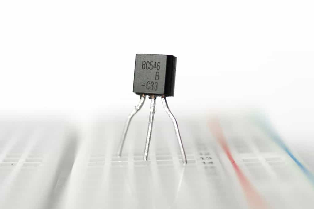
Let’s start with the classic NPN transistor. It’s a Bipolar Junction Transistor (BJT) and has three legs:
- Base (b)
- Collector (c)
- Emitter (e)
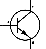
If you turn it ON, current can flow through it from the collector to the emitter. When it’s OFF, no current can flow.
In the example circuit below, the transistor is OFF. That means no current can flow through it, so the Light-Emitting Diode (LED) is also off.
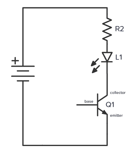
To turn the transistor ON, you need a voltage of about 0.7V between the base and the emitter.

Get Our Basic Electronic Components Guide
Learn how the basic electronic components work so that circuit diagrams will start making sense to you.
If you had a 0.7V battery, you could have connected it between the base and emitter, and the transistor would have turned ON.
Since most of us don’t have a 0.7V battery, how do we turn on the transistor?
Easy! The base-to-emitter part of a transistor works like a diode. A diode has a forward voltage that it “grabs” from the available voltage. If you add a resistor in series, the rest of the voltage drops across the resistor.
So you’ll automatically get around 0.7V by adding a resistor.
This is the same principle you use to limit the current through an LED to make sure it doesn’t blow up.
If you also add a pushbutton, you can control the transistor, and thereby the LED, ON and OFF with a button:
Choosing Component Values
To choose the component values, there’s one more thing you need to know about how transistors work:
When a current flows from the base to the emitter, the transistor turns on so that a larger current can flow from the collector to the emitter.
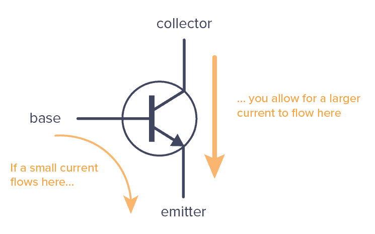
There is a connection between the sizes of the two currents. This is called the gain of the transistor.
For a general-purpose transistor, such as the BC547 or 2N3904, this could be around 100.
That means that if you have 0.1 mA flowing from the base to the emitter, you can have 10 mA (100 times more) flowing from collector to emitter.
What resistor value do you need for R1 to get 0.1mA flowing?
If the battery is 9V, and the base-to-emitter of the transistor grabs 0.7V, then there’s 8.3V left across the resistor.
You can use Ohm’s law to find the resistor value:
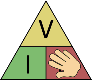

So you need a resistor of 83 kΩ. That’s not a standard value, but 82 kΩ is, and it’s close enough.
R2 is there to limit the current to the LED. You can choose the value you would have chosen if you were to connect the LED and resistor directly to the 9V battery, without the transistor. For example, 1 kΩ should work fine.
Check out the video explanation I made on the transistor a few years back (forgive the old-school quality):
How To Choose a Transistor
The NPN transistor is the most common of the Bipolar Junction Transistors (BJT). But there is another one called a PNP transistor that works the same way, just that all the currents are in the opposite direction.
When choosing a transistor, the most important thing to keep in mind is how much current the transistor can support. This is called the Collector Current (IC).
How a MOSFET Transistor Works
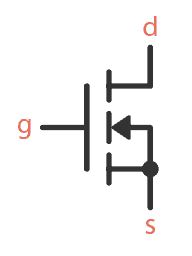
The MOSFET transistor is another very common type of transistor. It also has three pins:
- Gate (g)
- Source (s)
- Drain (d)
A MOSFET works similar to the BJT transistor, but with one important difference:
In the BJT transistor, the current from base to emitter decides how much current can flow from collector to emitter.
In the MOSFET transistor, the voltage between gate and source decides how much current can flow from drain to source.
Example: How To Turn ON a MOSFET
Below is an example circuit for turning on a MOSFET.
To turn a MOSFET transistor on, you need a voltage between gate and source that is higher than the threshold voltage of your transistor. For example, the BS170 has a gate-source threshold voltage of 2.1V. (You’ll find this info in the datasheet).
The threshold voltage of a MOSFET is actually the voltage where it turns off. So to turn the transistor properly on, you need a voltage a bit higher than that.
How much higher depends on how much current you’d like to have flowing (and you’ll find that info in the datasheet). If you go a couple of volts above the threshold, that’s usually more than enough for low-current things like turning on an LED.
Note that even if you use a high enough voltage to have 1A current flowing, it doesn’t mean you’ll get 1A. It just means that you could have 1A flowing if you wanted to. But it’s whatever you connect to it that decides the actual current.
So you can go as high as you want, as long as you make sure you don’t go above the maximum gate-source voltage limit (which is 20V for the BS170).
In the example above, the gate is connected to 9V when you push the button. This turns the transistor on.
Choosing Component Values
The value of R1 isn’t crucial, but around 10 kΩ should work fine. Its purpose is to turn off the MOSFET (more about that below).
R2 sets the brightness of the LED. 1 kΩ should work fine for most LEDs.
Q1 could be almost any n-channel MOSFET, for example, BS170.
How To Turn OFF a MOSFET?
One important thing to learn about the MOSFET is that it also acts a bit like a capacitor. That is, the gate-source part. When you apply a voltage between gate and source, this voltage stays there until it’s discharged.
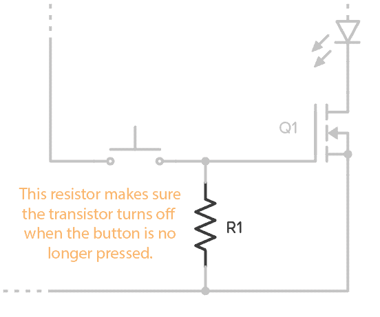
Without the resistor (R1) in the example above, the transistor wouldn’t turn off. With the resistor, there is a path for the gate-source capacitor to discharge so that the transistor turns off again.
How To Choose a MOSFET Transistor
The above example uses an N-channel MOSFET. P-channel MOSFETs work the same way, just that the current flows in the opposite direction, and the gate to source voltage must be negative to turn it on.
There are thousands of different MOSFETs to choose from. But if you want to build the example circuit above and want a specific recommendation, BS170 and IRF510 are two commons ones.
Two things to keep in mind when choosing a MOSFET is:
- The gate-to-source threshold voltage. You need a voltage higher than this to turn the transistor on.
- The Continuous Drain Current. This is the maximum amount of current that can flow through your transistor.
There are other important parameters to keep in mind, depending on what you’re making. But that’s out of the scope of this article. Keep the two parameters above in mind and you’ll have a good starting point.
MOSFET Gate Current
If you want to control a MOSFET from for example an Arduino or Raspberry Pi, there is another thing you need to keep in mind; the current that flows into the gate when you turn the transistor on.
As briefly mentioned above, the gate-to-source of a MOSFET acts as a capacitor.
That means once it’s charged, no more current flows through it. So when a MOSFET is on, there is no current flowing through the gate.
But when a MOSFET is being turned on, there is a current, just like when you charge a capacitor. For a small fraction of a second, there can be a lot of current flowing.
To protect your Arduino (or whatever you’re using) from too much current, you need to add a MOSFET gate resistor:
Often 1000 Ω is a good enough value for this. Use Ohm’s law to check for your specific case.
Why Do You Need A Transistor?
A common question I get is why do we need the transistor? Why not connect the LED and resistor directly to the battery?
The advantage of a transistor is that you can use a small current or voltage to control a much larger current and voltage.
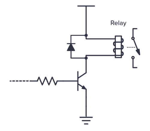
That’s super useful if you want to control things like motors, high-power LEDs, speakers, relays, and more from a Raspberry Pi/Arduino/microcontroller. The output pins from these boards can usually only provide a few milliamperes at 5V. So if you want to control your 110V outdoor patio lights, you can’t do it directly from the pin.
Instead, you could do it through a relay. But even the relay usually needs more current than the pin can provide. So you’d need a transistor to control the relay:
But transistors are also useful for simpler sensor circuits, like this light sensor circuit, the touch sensor circuit, or the H-Bridge circuit.
We use transistors in almost all circuits. It’s really the most important component in electronics.
The Transistor as an Amplifier
The transistor is also what makes amplifiers work. Instead of having just two states (ON/OFF) it can also be anywhere in between “fully on” and “fully off”.
That means a small signal with almost no energy can control a transistor to create a much stronger copy of that signal in the collector-emitter (or drain-source) part of the transistor. Thereby, the transistor can amplify small signals.
Below is a simple amplifier to drive a speaker. The higher the input voltage, the higher the current from base to emitter, and the higher the current through the speaker.
A varying input voltage makes the current in the speaker vary, which creates sound.
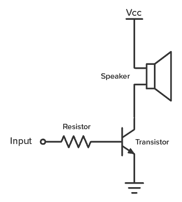
Normally, you’d add a couple of more resistors to bias the transistor. Otherwise you’ll get a lot of distortion. But that’s for another article.
If you want to learn more about using the transistor as an amplifier, electronics-lab.com has some nice tutorials that go through the three basic BJT amplifier setups.
Questions?
Do you understand how transistors work now? Or are you still confused? Let me know in the comments below.
More Transistors Tutorials
Get Our Basic Electronic Components Guide
Learn how the basic electronic components work so that circuit diagrams will start making sense to you.

